Final Project – Alarm Clock
The Idea
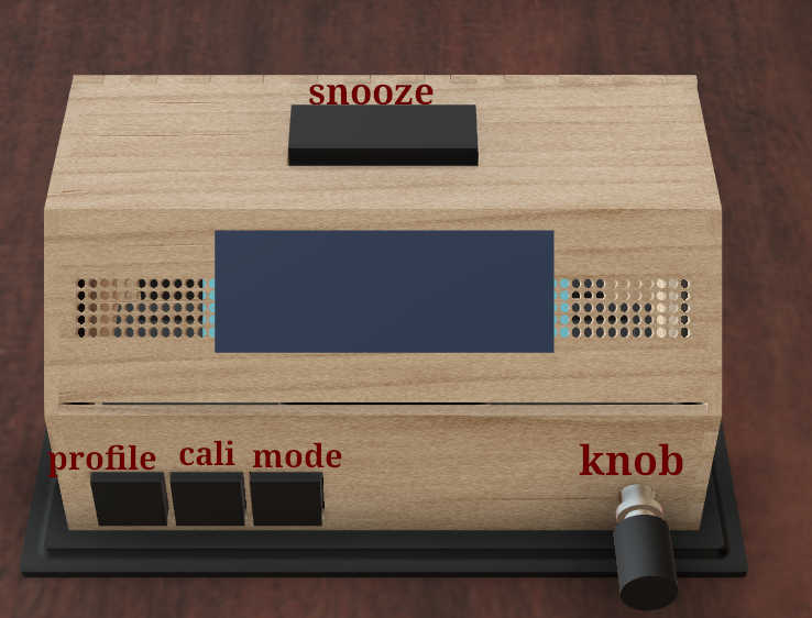
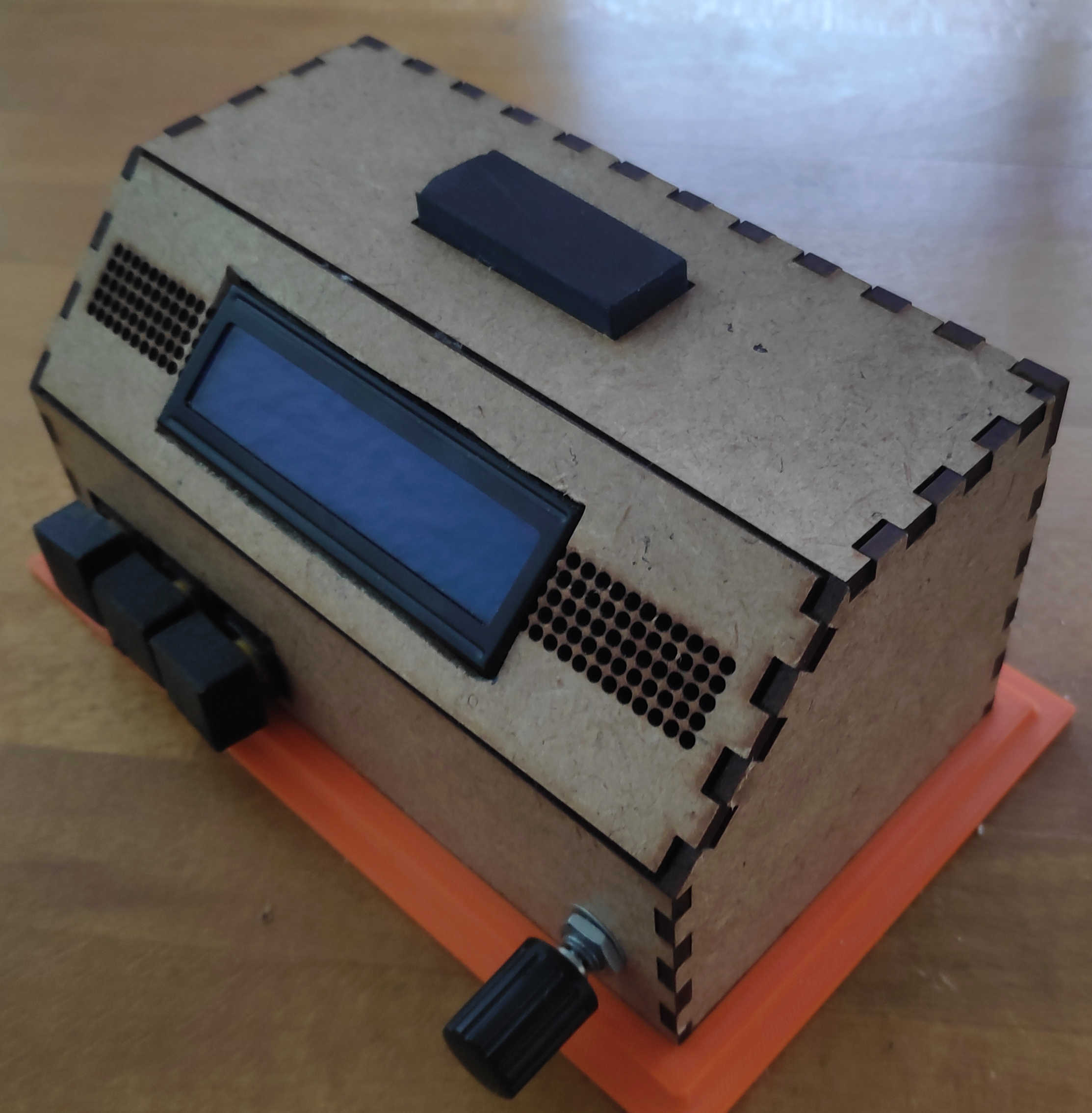
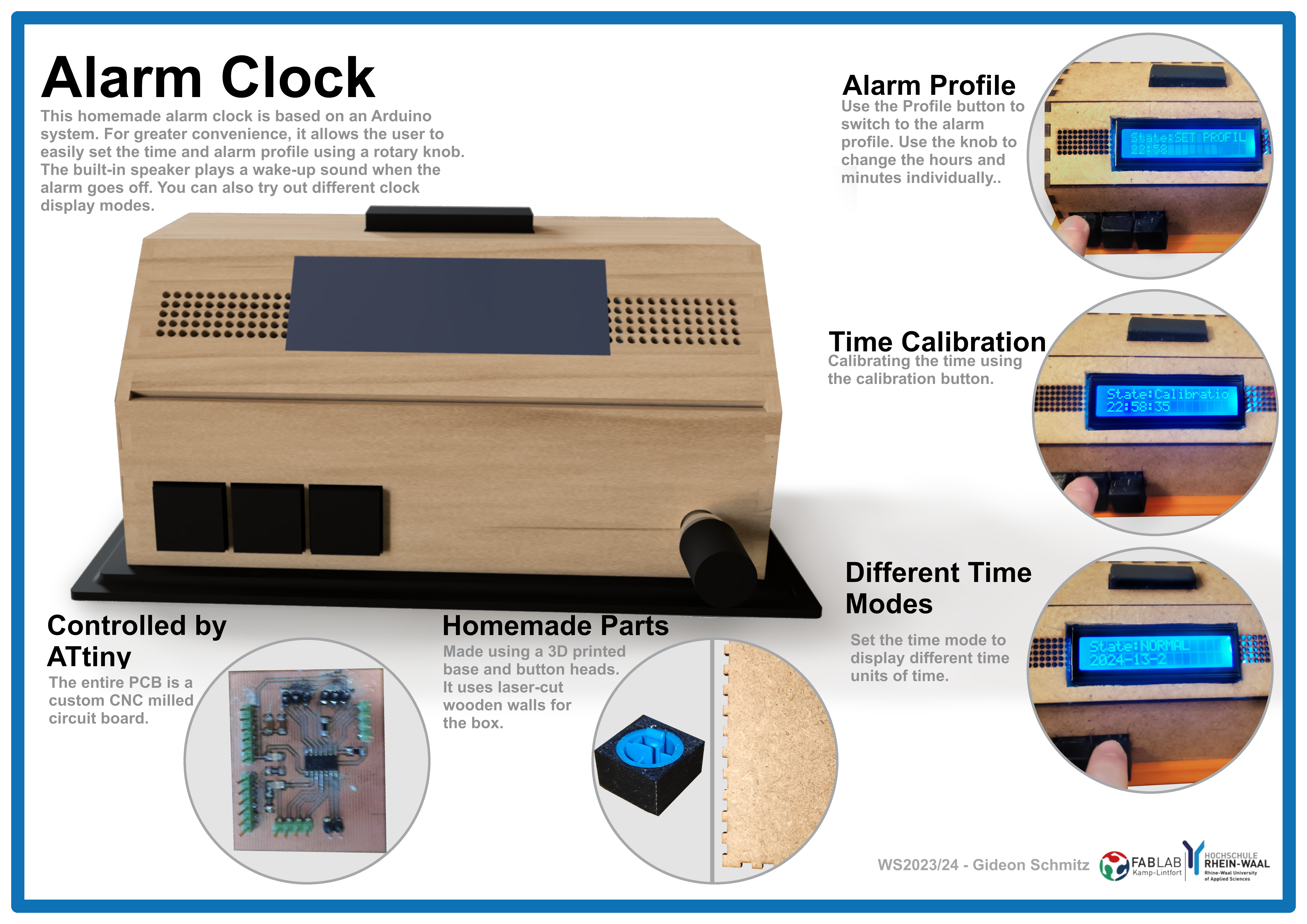
For the final project, I decided to build an alarm clock. This alarm clock has the functions of displaying time and triggering an alarm, when a certain time is reached. The alarm can be switched off by pressing the snooze button. The time of the clock can be set manually by pressing a calibration button. The alarm-profile can likewise be adjusted by pressing a calibration button and setting it to the wanted time. Furthermore the clock can change change the display mode by pressing the mode button. Finally, a rotatory knob can be used to adjust how loud the speaker should be. It can also be used in combination with one of the calibration modes to set the time of the clock or alarm-profile.
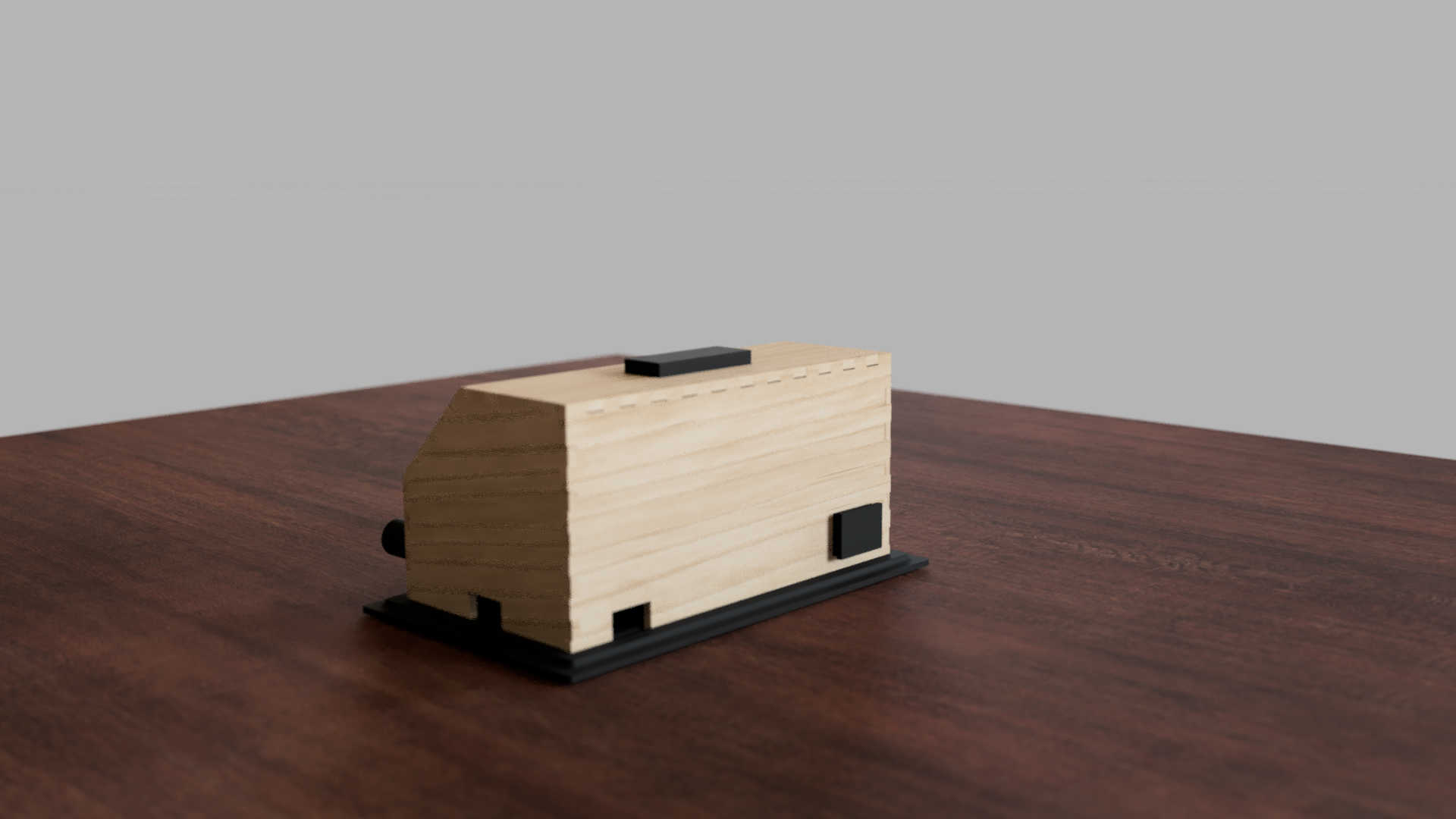
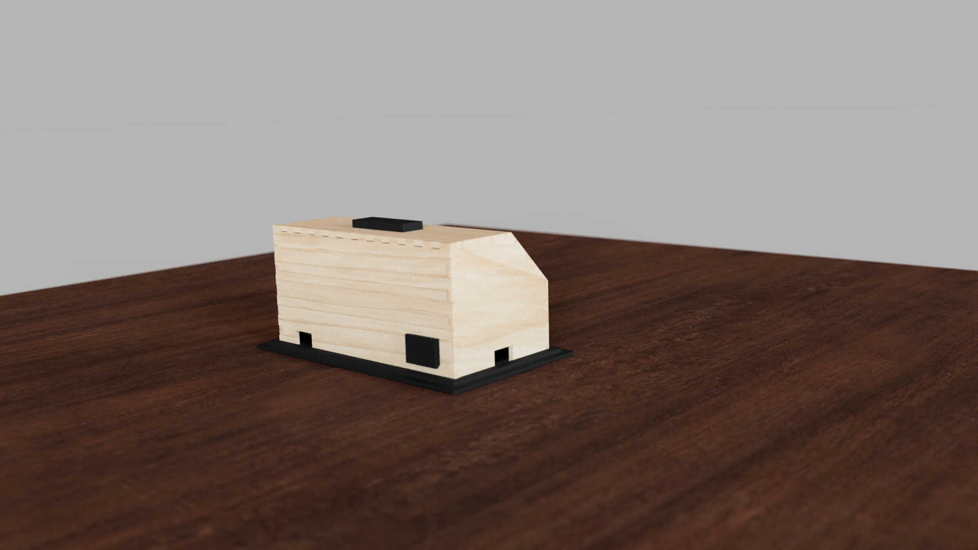
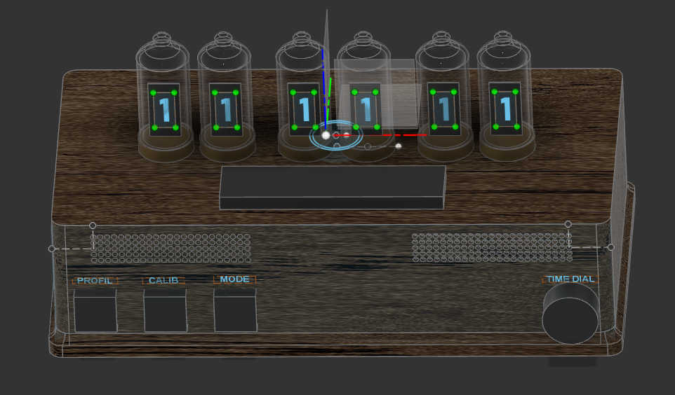
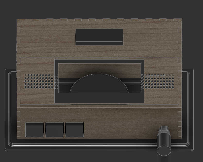
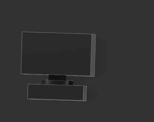
As a containment I designed Box using Fusion 360. I began by making a rough 3d model to deiced the placement for each component. The box, which I would used, should fit all PCBs and the speaker. For the main box itself I decided to make a box shape. I made different variation, which I could later decide on in the process. Looking back at the different design's for the final project, it changed very much between each phase.
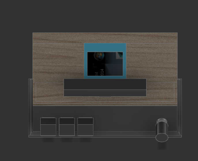
First, I designed the box for a 7-segment, which displayed for display a digit. For the second design, wanted to switch to an OLED display, so I had to make space for just a singular Display. I also changed the button layout a bit to have a better access to the stop button. I tilted the display a bit to have a better view from top and side view. The final design I landed uses press fit walls, which changed a bit the wall sizes and placements. Furthermore I switch from an OLED to an LCD Char display, which I will later expand on.
The 3d Design
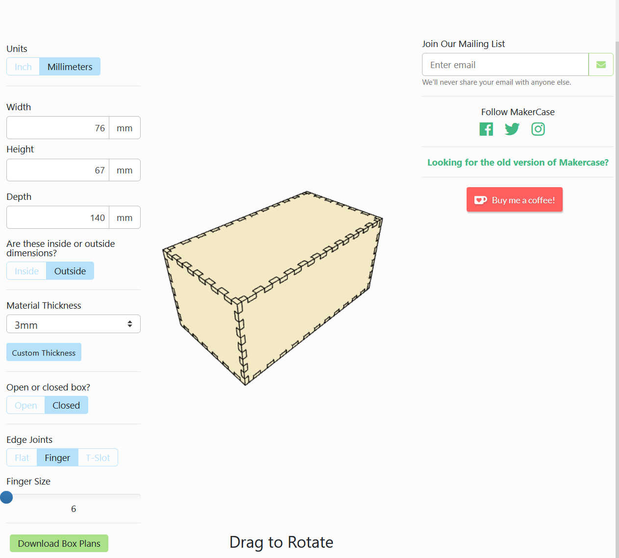
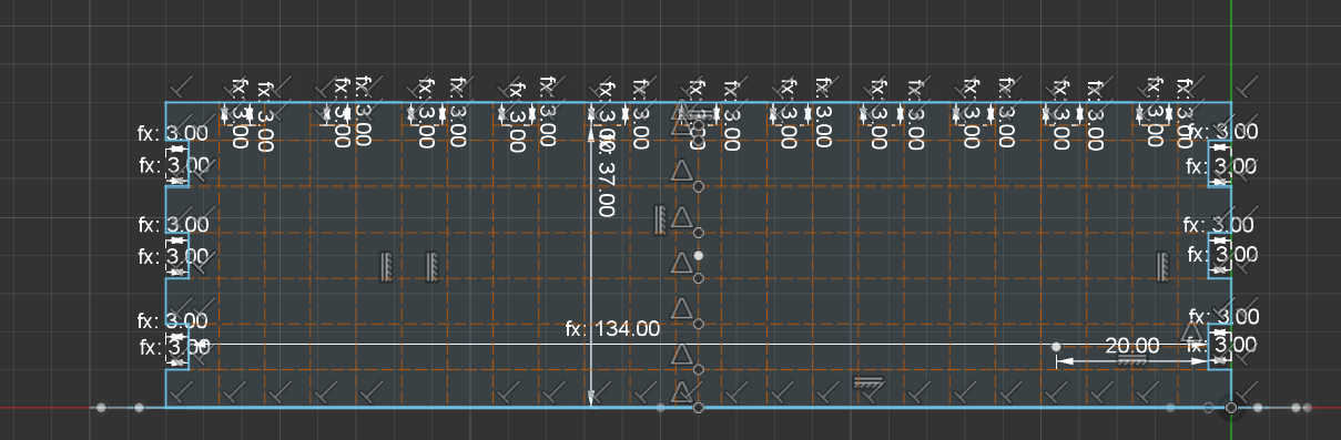
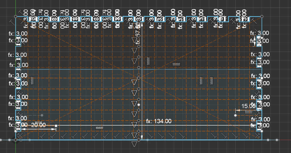
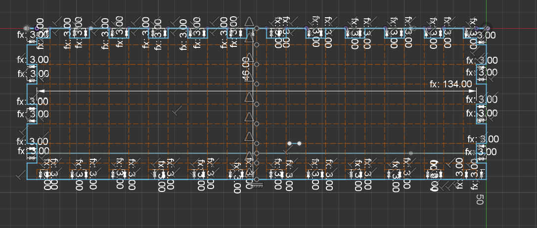
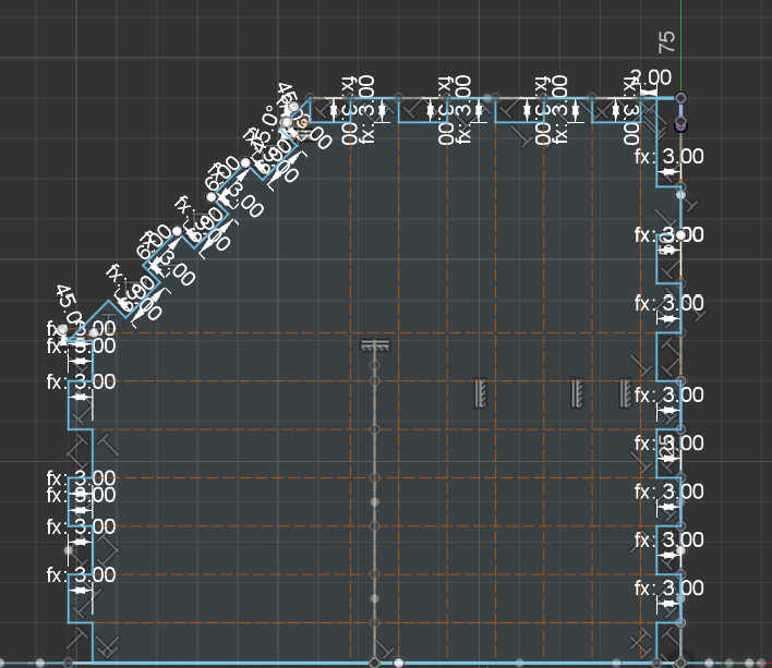
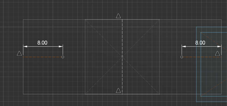
For the final design I downloaded a simple shaped Box from “makercase.com” that had the same dimensions as my design. I used the walls provided of this box to make a press fit model. I started of with a sketch based on the finger-pattern designed with 6mm spacing between each finger. Where the angles were not 90 degrees, I made the fingers myself, using the same finger size as the base. Each sketch was than extruded to check that everything fitted.
At the first stage of the 3d model, I designed a rough shape for each component that was the same size as the real components. I only used important features, such as the size of the PCB or diameter of the rotary encoder, which I can use later for sizing the cut-outs on the walls.

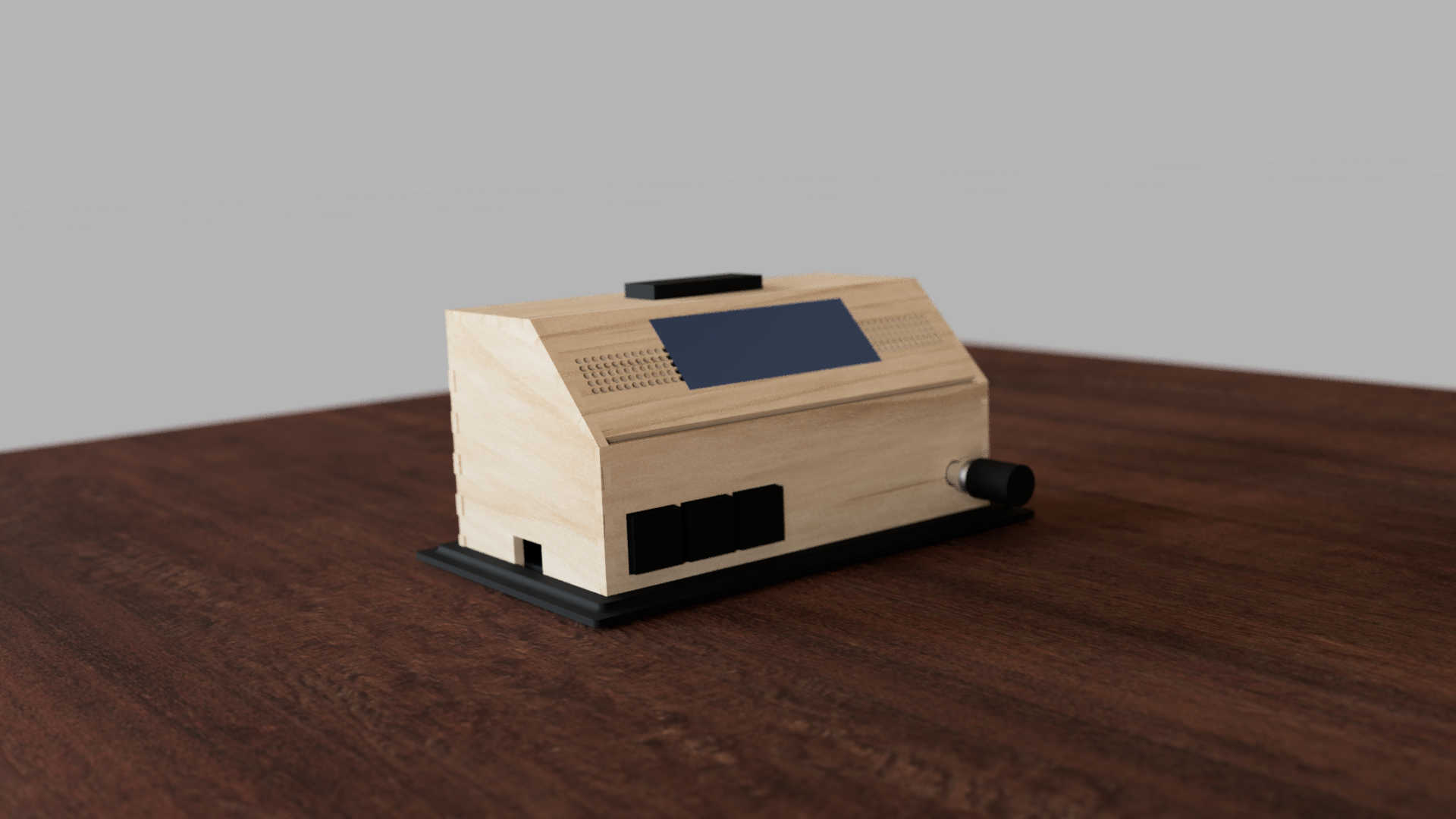
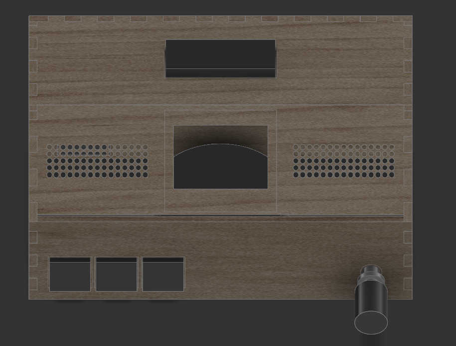
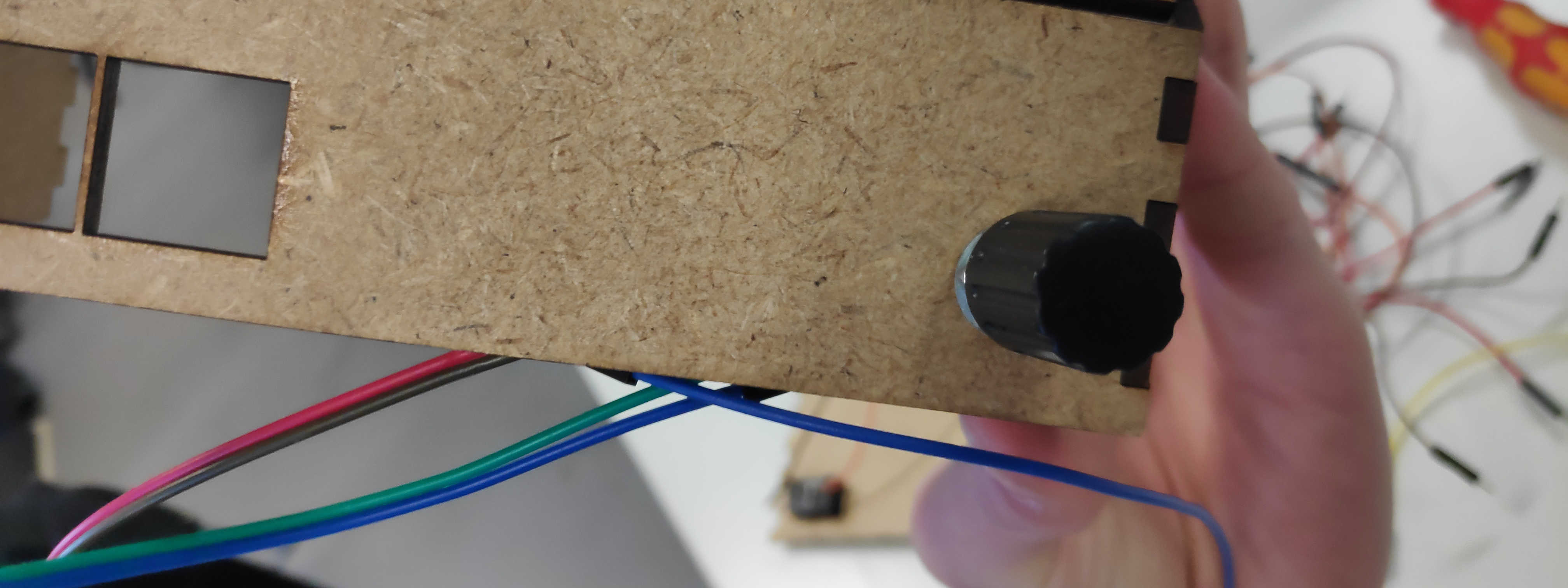
For the front face I use the imported box to cut out some holes by creating a sketch and than clustering it, to make space for the 3 main buttons. On the same wall, I made a circular cut-out for a rotary encoder. The encoder can later be screwed to the wall itself.
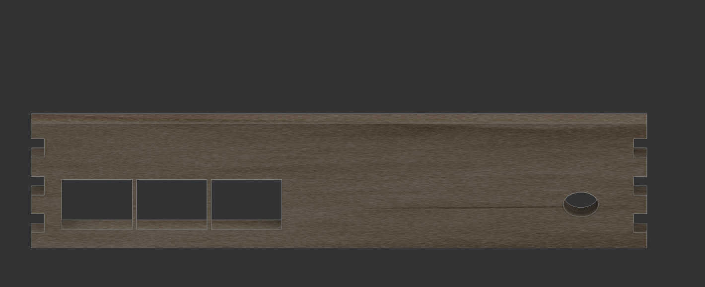
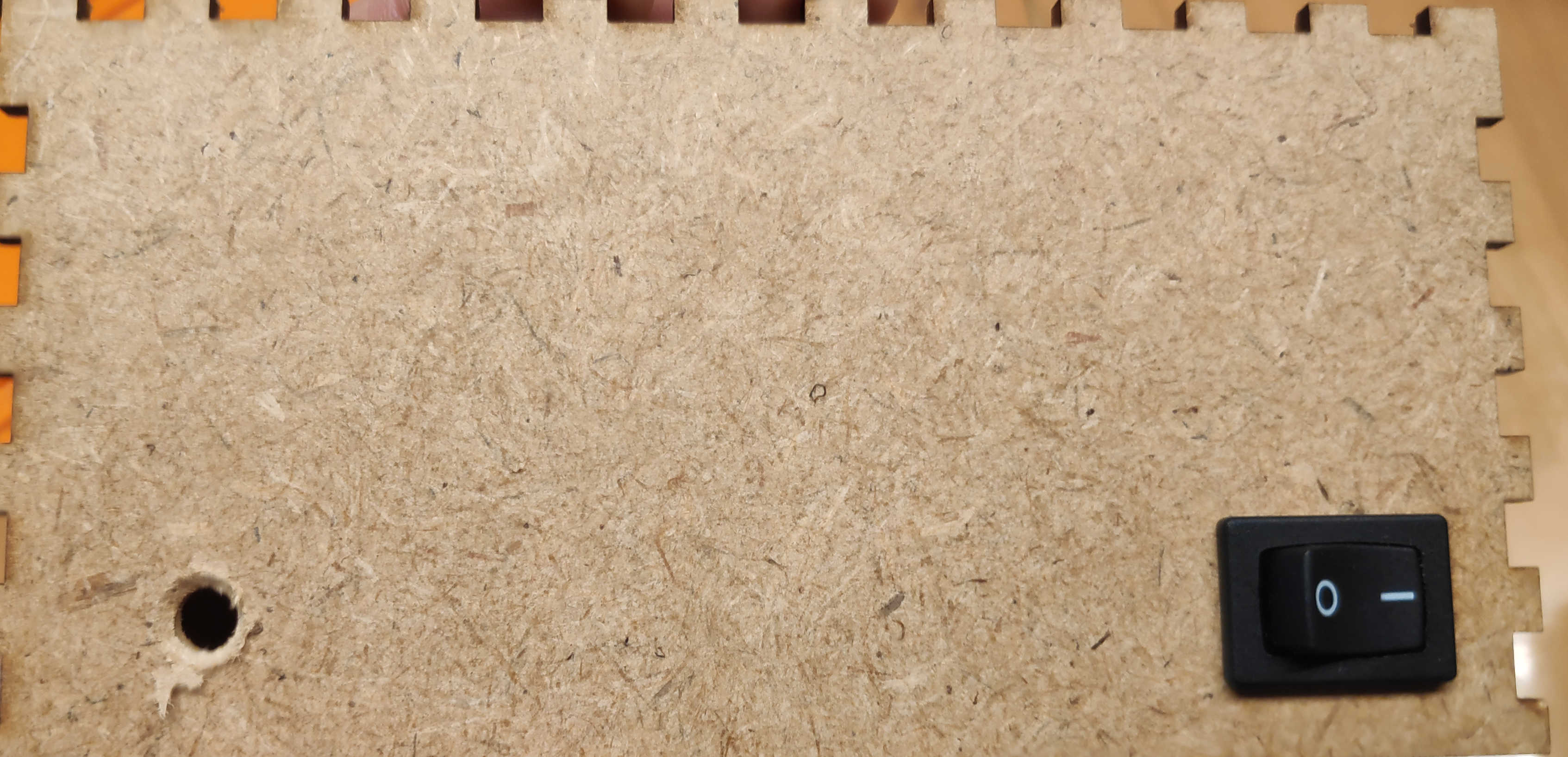
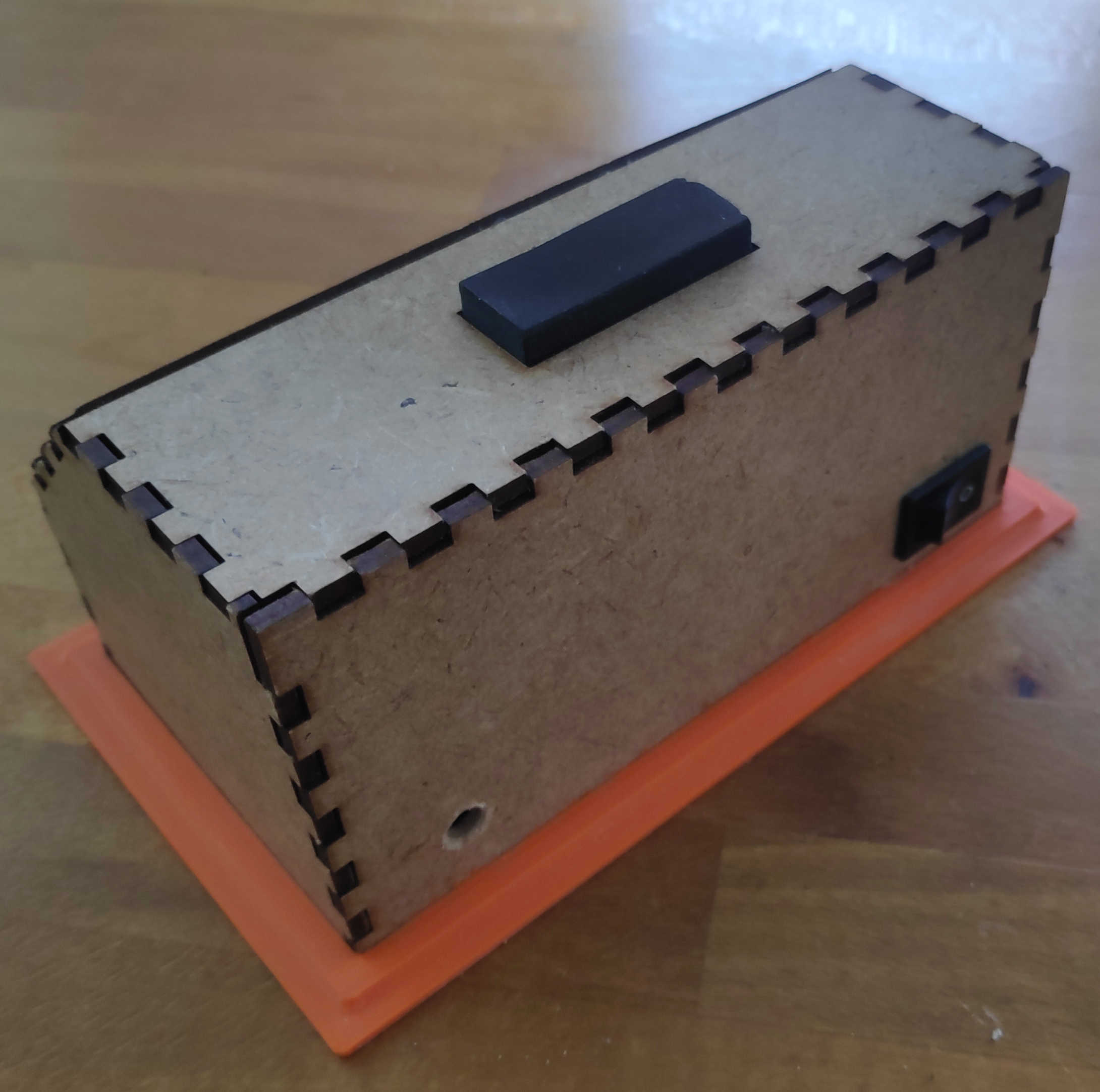
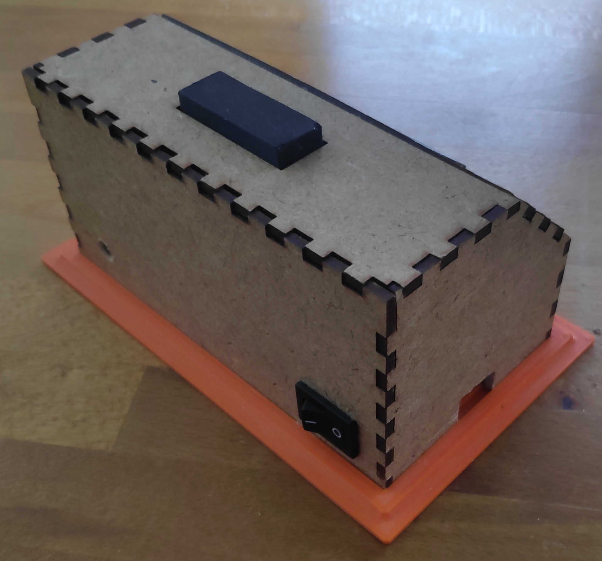
Next face was the backside on which I cutout a rectangular shape to fit an off switch inside. Here a cut-out can be made for a charging module by creating a rectangular shape in the size of USB-C port. If USB-port doesn't protrude beyond the PCB, enlarge the cut-out so a USB-C cable fit through it.

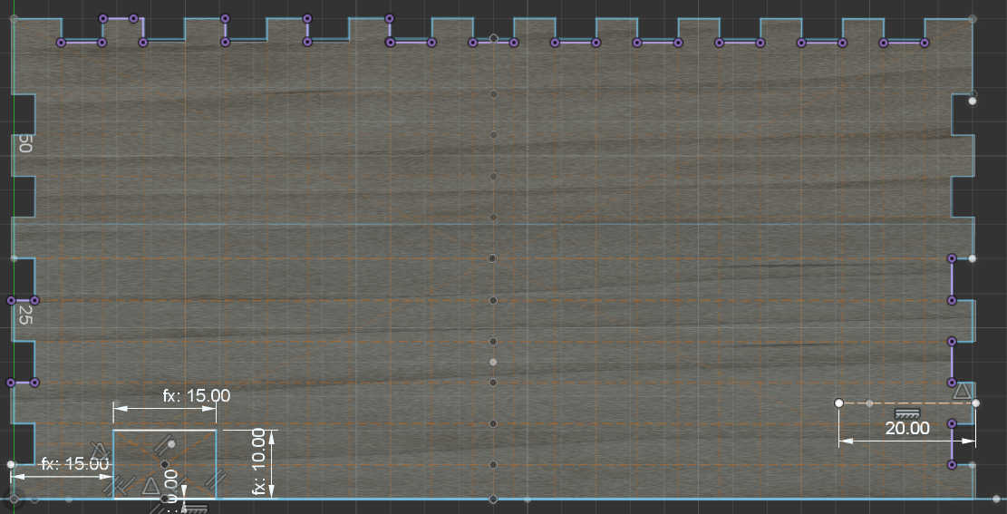
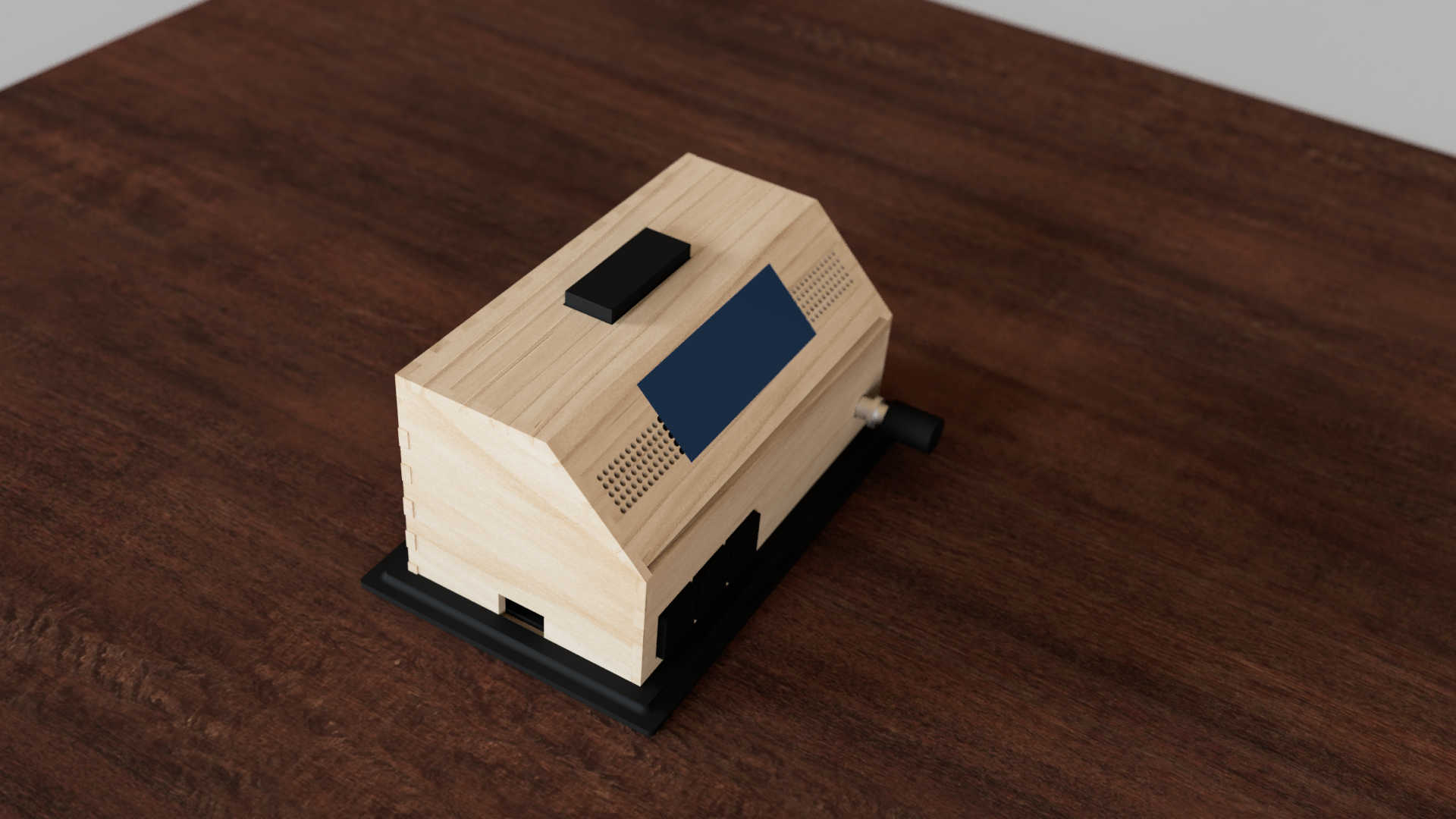
I created two walls for the top-side. The first wall is 90-degree angle to the back wall and is used for the placement of the snooze button. This button is larger than the other buttons, thus I made a larger cut-out on the top. I wanted place this button here, so it wouldn’t be touched accidentally.
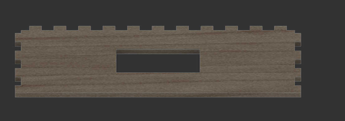
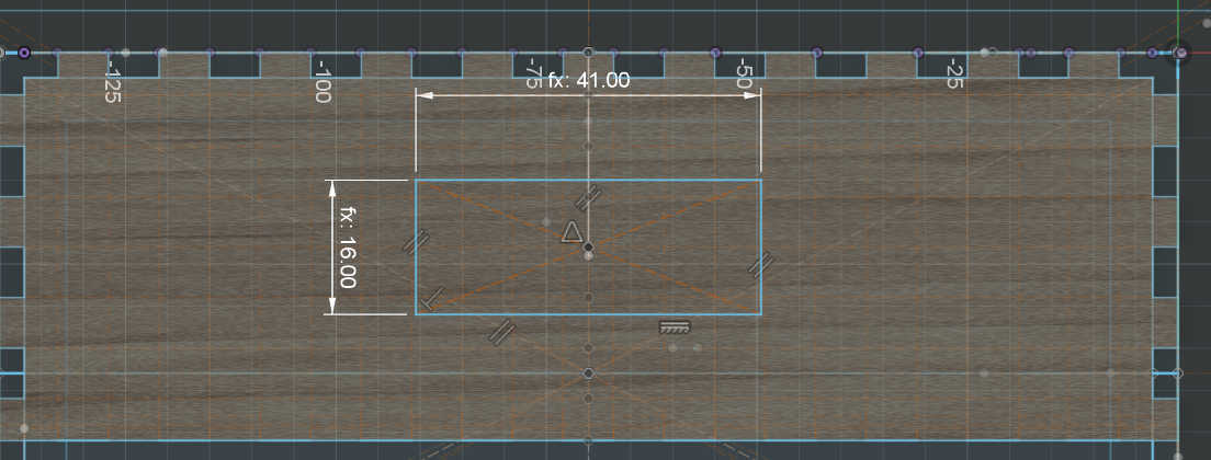
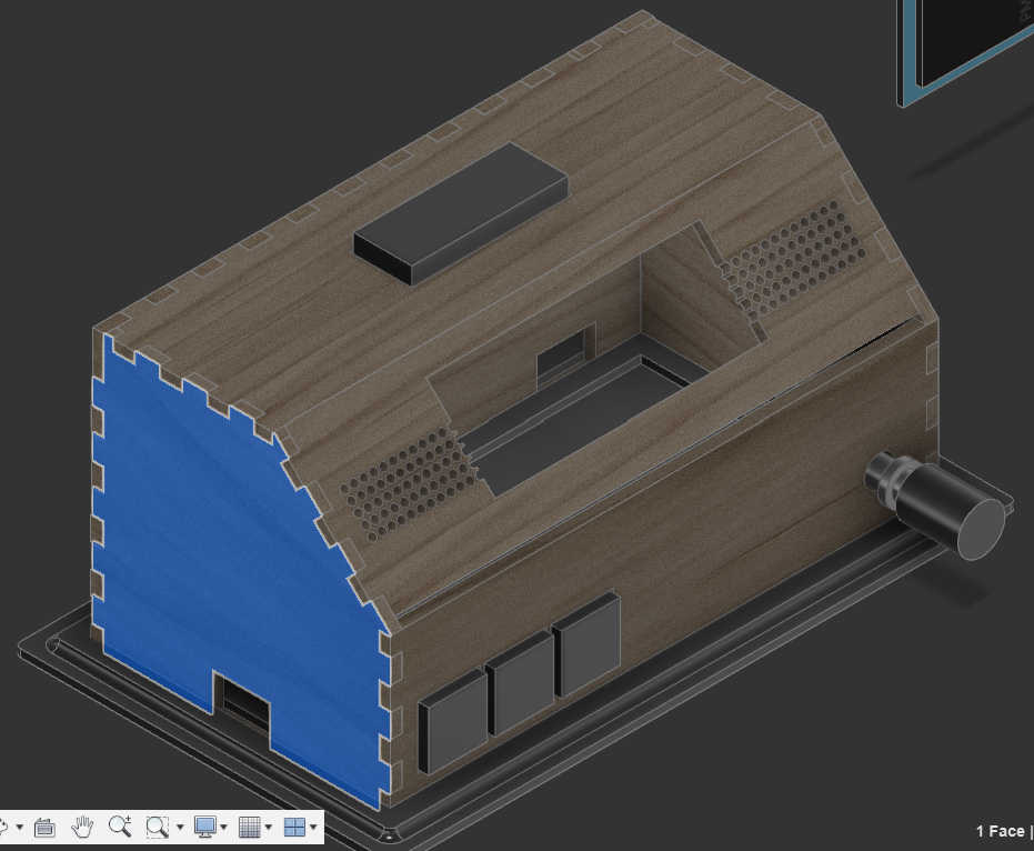
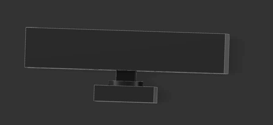
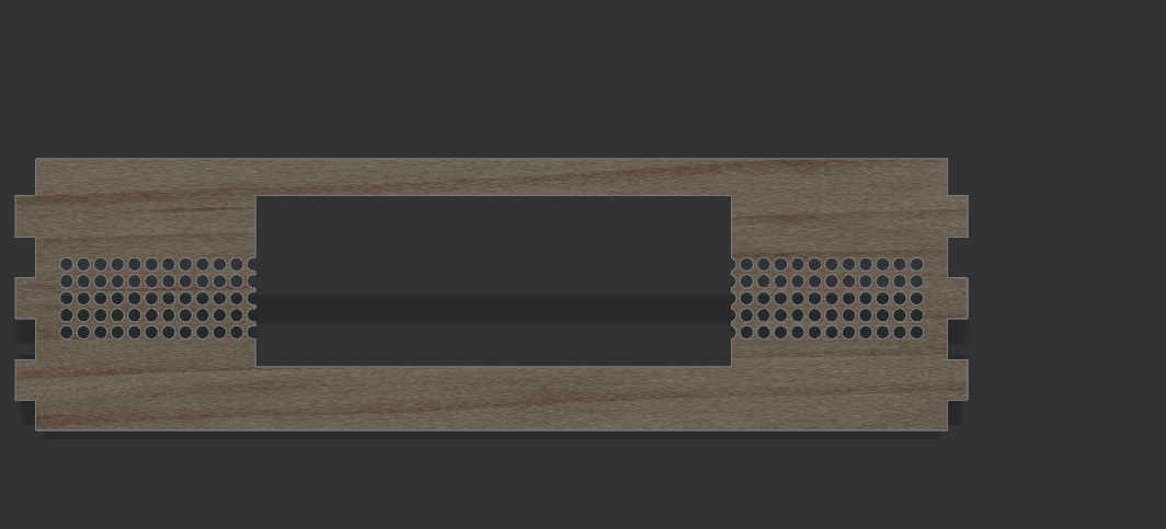
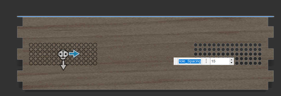
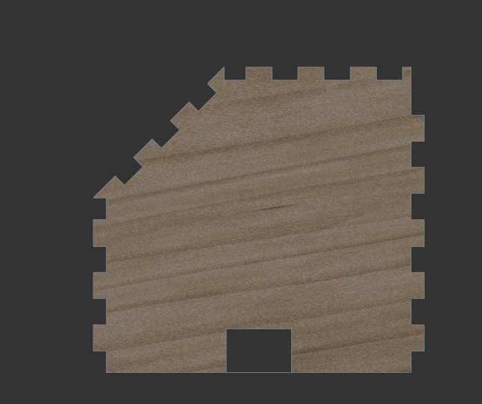
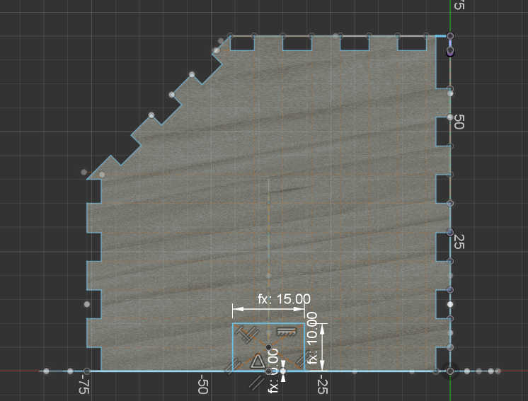
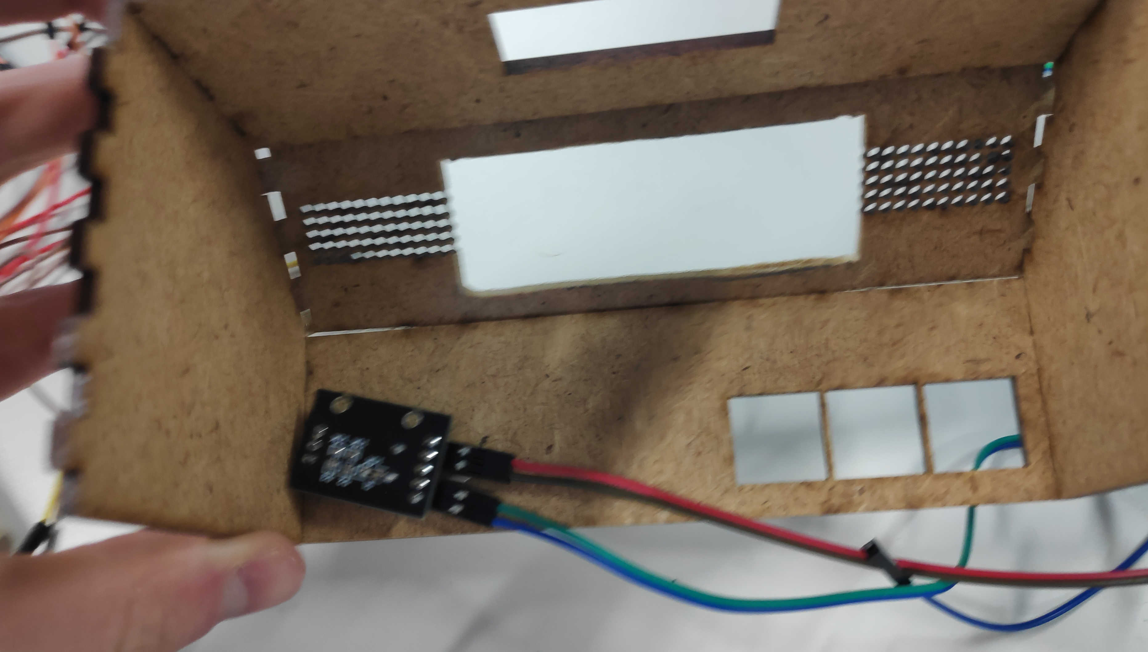
The other top plain is 45deg to the front wall. This made it difficult to place the fingers as the angled display should overlap with the top and side panels. I solved the problem by removing the top and bottom fingers from this wall to simply wedge them in. I used this wall mainly for the display. I made a cut-out the size of the display frame. This made it better to look at and helps later when mounting the display. Another 2 cut-outs symmetrically to another are the speaker holes through which the sound waves of the speaker can travel. This wall has to be adjusted depending on the screen size and screen to be used.

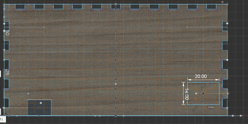
The last to walls, left and right are practically the same wall. Each wall was designed as before, but I also had to keep the 45-degree angle from the top wall. This meant, that the fingers needed to place in an angle for this wall. After finishing one side, I copied the 3D model to place it on the other side. This wall could alternatively be used for a charging module, so I made an adjustable cut-out.
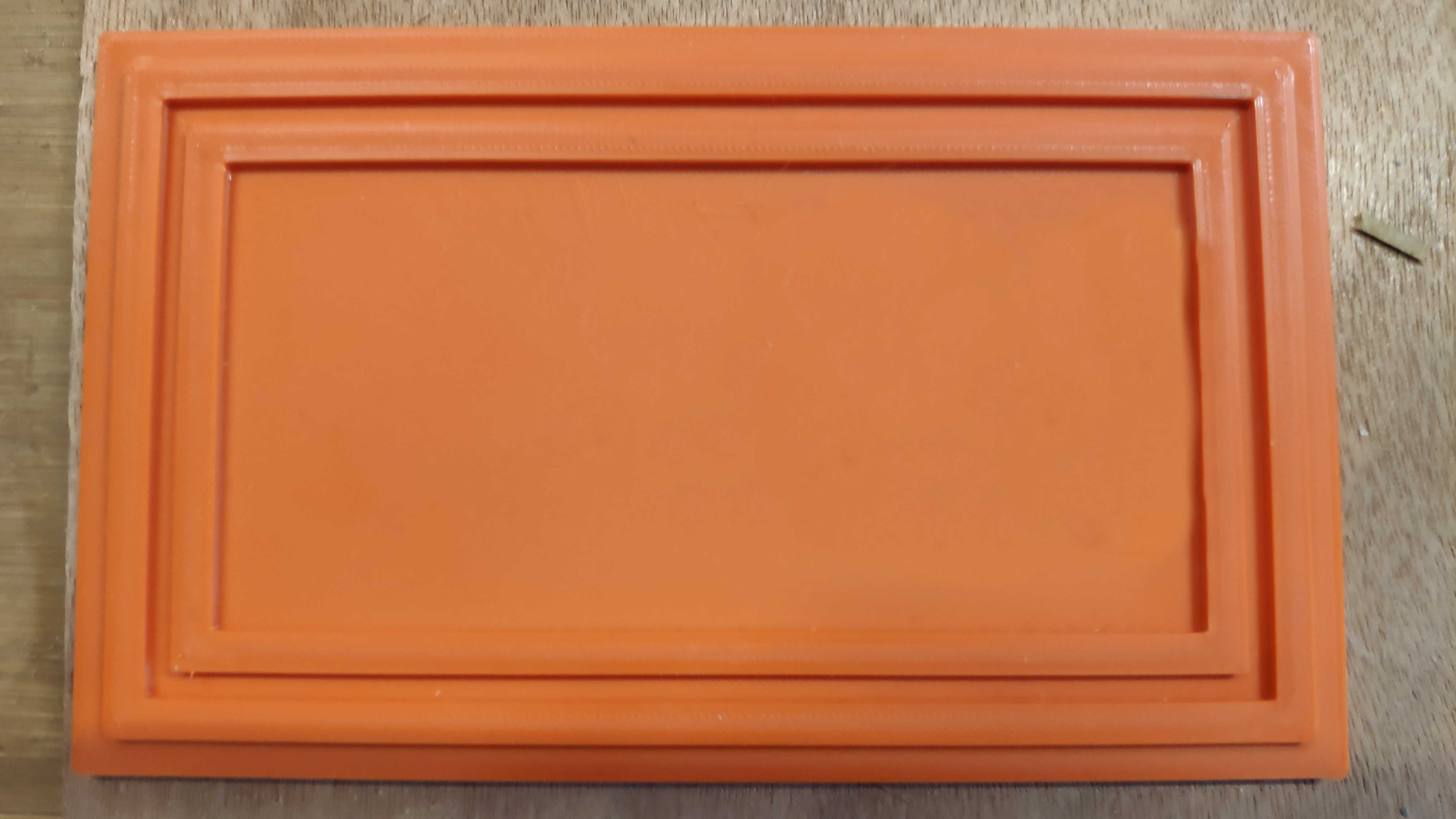
For the bottom plate I decided to 3d-print it, so I can make a 3d-shape. I created a bottom plate with 2 walls to hold the Box together at the bottom. I created adjustable parameters for the bottom plate to change them if the print is not that accurate.
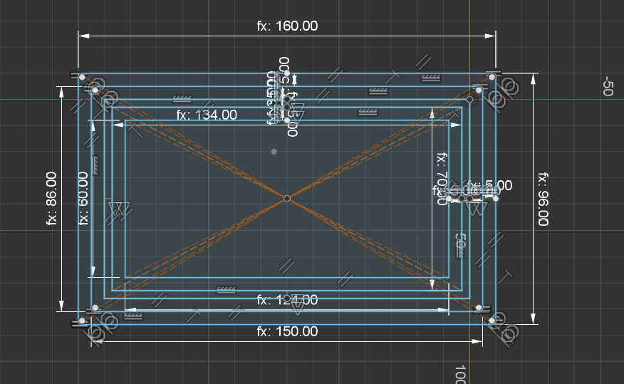
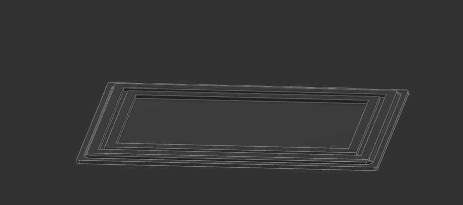
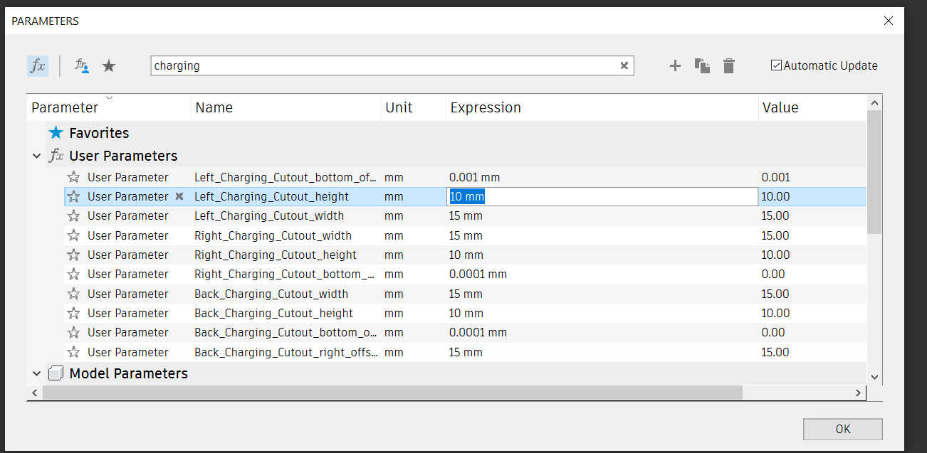
I tried to parameterize the entire 3D model, but this only works to adjust the size a little because the fingers don't scale. To remove the cutouts of the charger from the model, chang the parameter size of <direction>_Charging_Cutout_height, <direction>_Charging_Cutout_height and <direction>_Charging_Cutout_bottom_offset to 0 to disabled unwanted cuts or scale it to the wanted size.
Laser Cutting
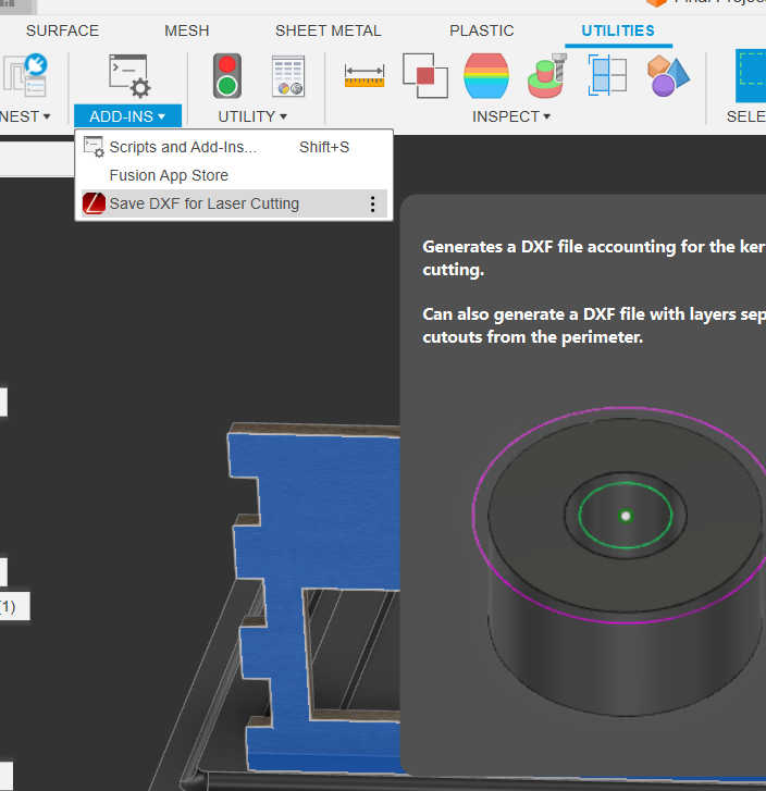
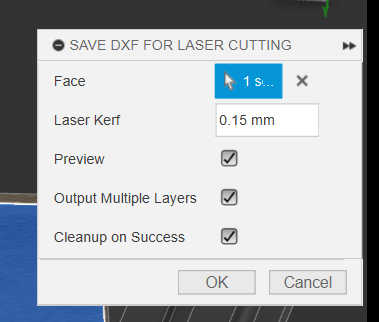
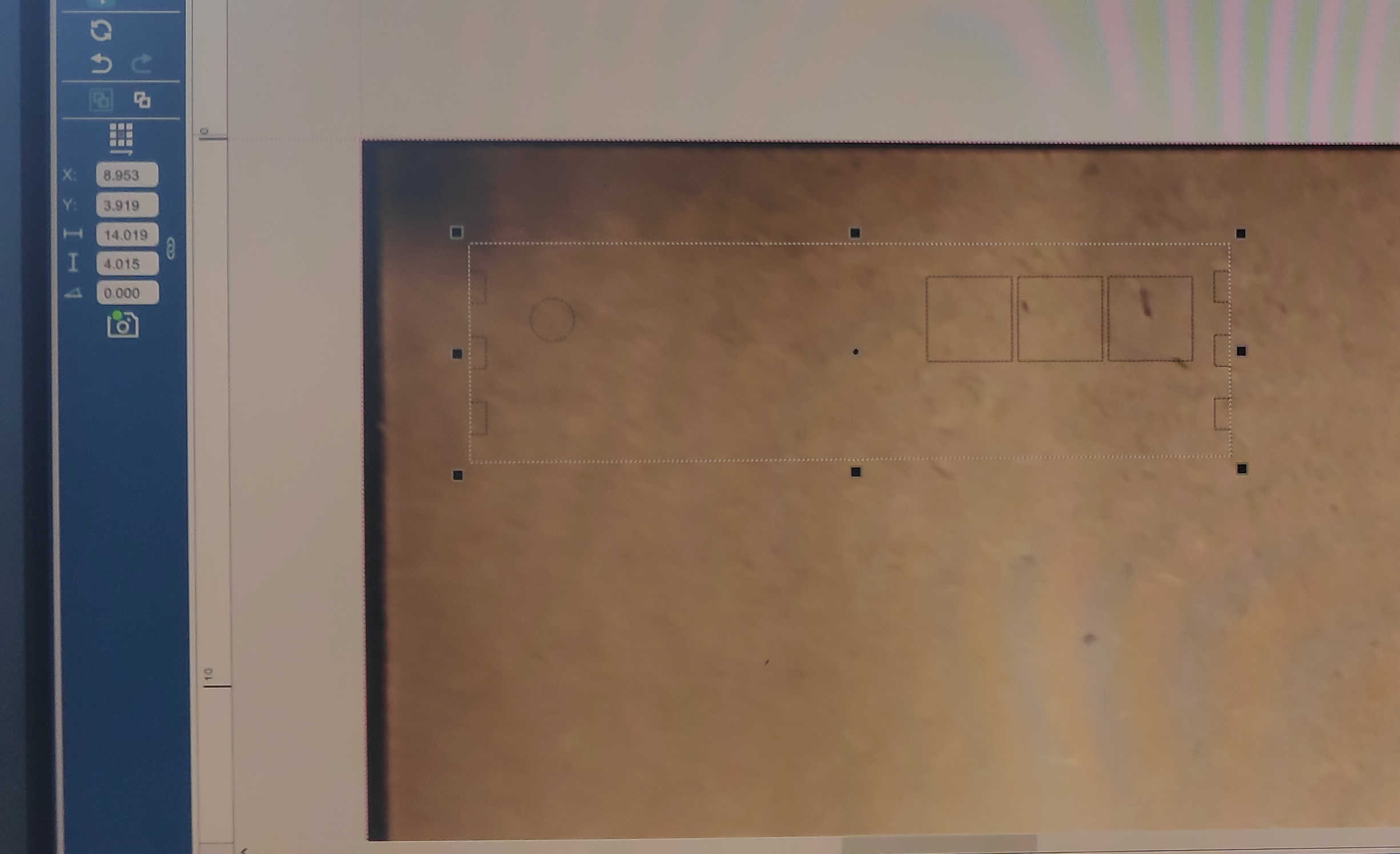
To get from the 3d model to the real model, you have to export the faces of each side of the model as an .dxl file. I used a “fusion” plugin called “DXF for Laser Cutting” to export it for the laser cutter. I used a Laser Kerf of 0.15mm.
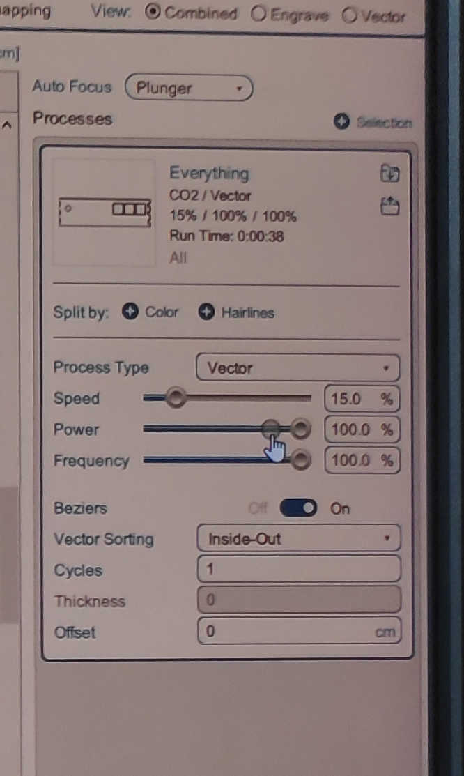
For the laser cutter I imported each file into “Rhino” and press print. This will open up the laser cutter menu for “Epilog”-Laser Cutter, if connected. I than placed each wall on the wood and used following settings. For the LASER Auto Focus, I selected “Plunger” and set the process Type to “Vector” as I wanted it to cut through the wood. Next, I set the vector Sorting to “Inside Out” thus the cutouts wouldn’t be unaligned. And finally, I set the material setting to speed 15%, power 100% and frequency to 100%. This should be enough to cut through a 3mm wooden panel. Don’t forget to turn on the fan for the laser and watch the laser cutter during the whole process.
The wooden walls are assembled by pressing each piece together. I recommend starting with the front panel and pressing the left and right wall together. Follow this up with the top and than the 45- degree Display Panel. Finally, press the back wall against the box. Be aware that you should put the the back plate on after all PCB components are in place.
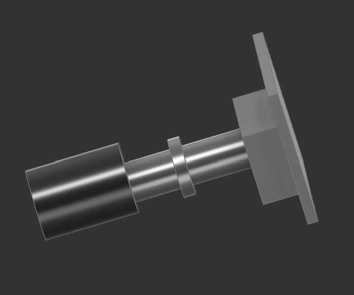
Button Heads
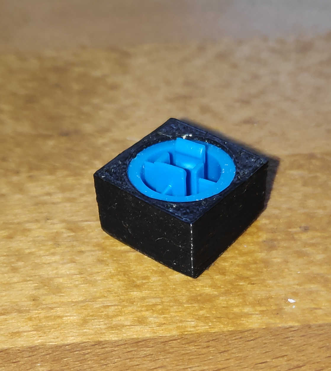
The last models I made were some custom button heads to fit on top of the original button heads, which are delivered with the buttons. I needed 3 square buttons for the front. I made a simple sketch of a cube and cut out the size of the original button head with the combine tool.


I needed 2 Buttons for the bigger button head, which made it easier to press it down. I made a rectangular sketch which I then extruded. Then I cutout the button with the original button head model on each side. Its important to keep in mind that i used a cutout model without tolerances to create the cut-outs. This makes the button press fit, but also relies on the precision of the 3d printer.


3d Prints
I send the Button-models to the 3d print with using 20% infill for the buttons as the shell alone had enough density. The resolution was set to 0.2mm fine and activated printed it with adhesion. No support was needed because I turned the model on its backside. All the buttons together in one print took about 30 min to print. For this process I used a Prusa 3D printer. Fitting the button heads was easy, as I only had to insert the original button head into the new one and press it down with enough force.
Settings:
- 20% infill
- 0.2mm
- Durtation: 30min
For printing the bottom of the box, I used PETG to make it more stable than with PLA. I also increased the strength by setting the print to 50% Infill. For the print-fines, I used a resolution of about 0.2mm. With this setting the print took around 2h to print.
Settings:
- 50% Infill
- 0.2mm
- PETG
- Durtation: 2h
PCBs
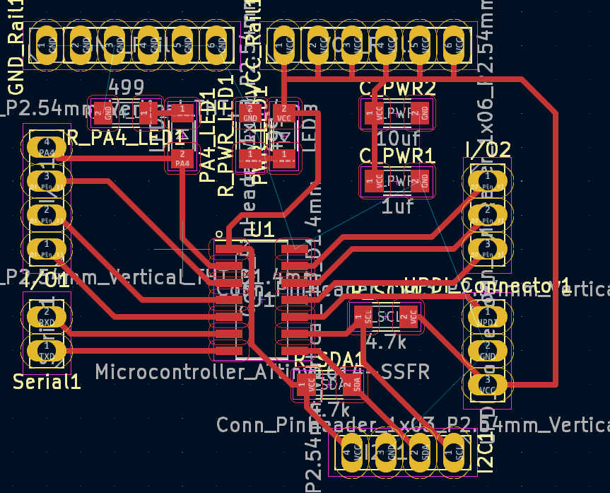
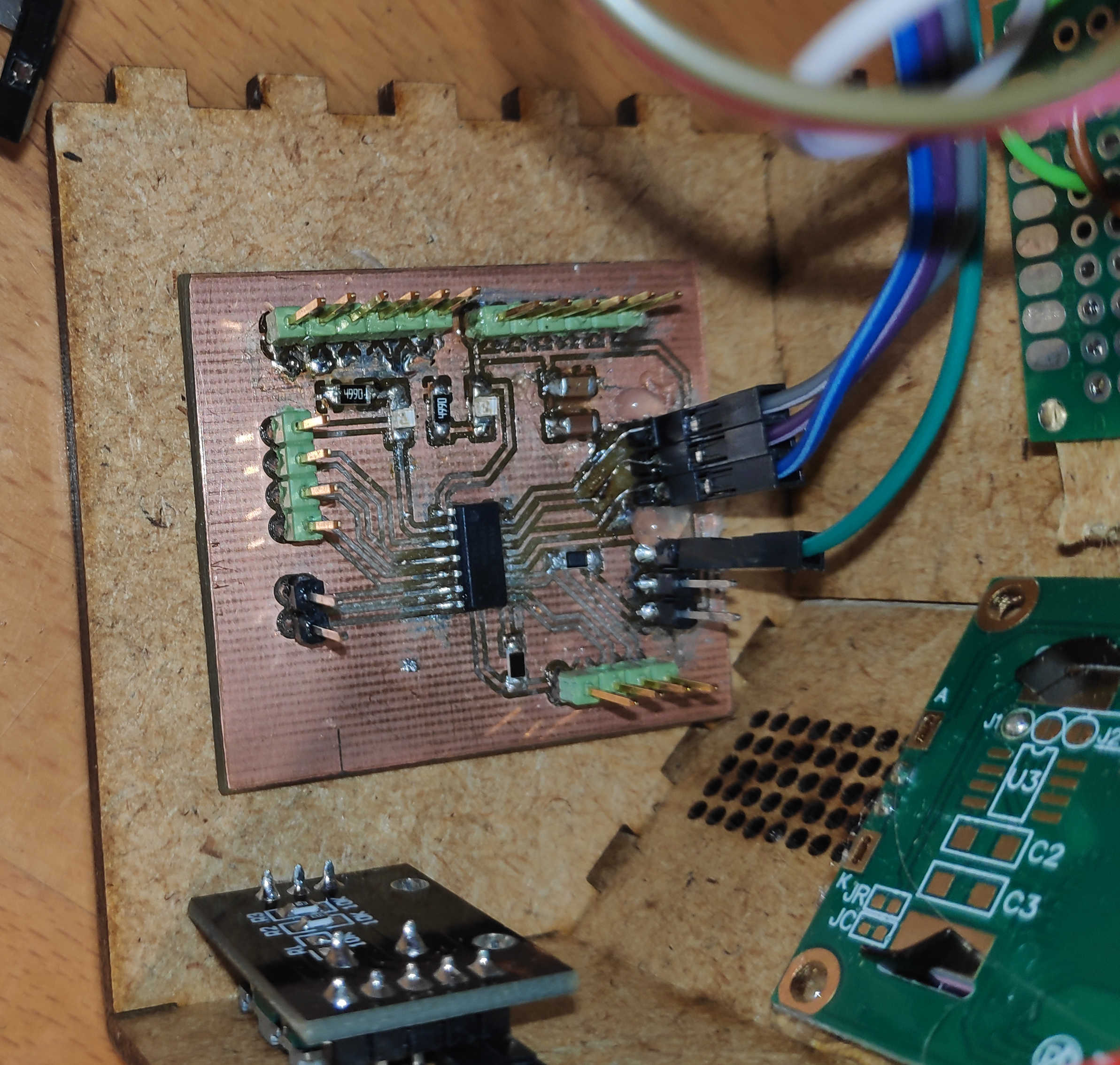
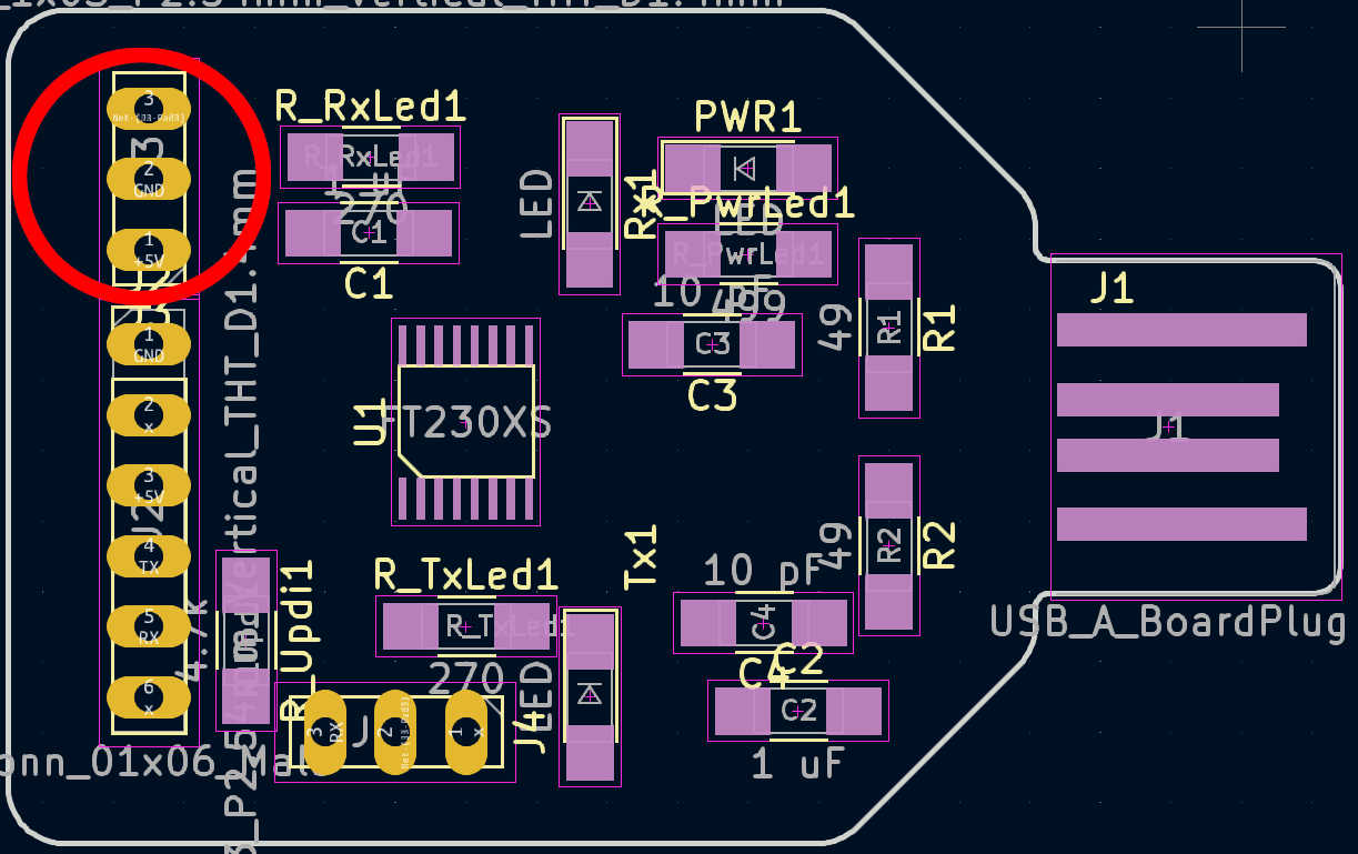
Now let's move on to the electrical side of the project. The main PCB is the same design and
construction as
in week 10, which can be seen in detail here: Week 10. It uses an
attiny1614 to
control all the logic. A Power source is required, which can be provided externally via the
programmer
or a battery. The module has an I2C connection, 7 digital pins and built-in LEDs on the power supply
and
on pin PA4. This makes the PA4 pin only available for write operation and not read operation.
Further detail on the Pin’s of the Attiny can be found under inside this Datasheet:
Datasheet
For the specific uses in combination with Arduino can be found here:
Pin-config
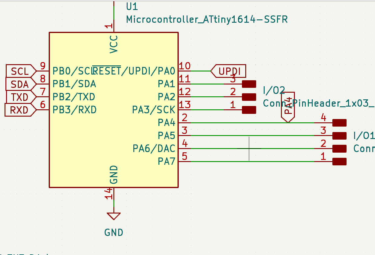
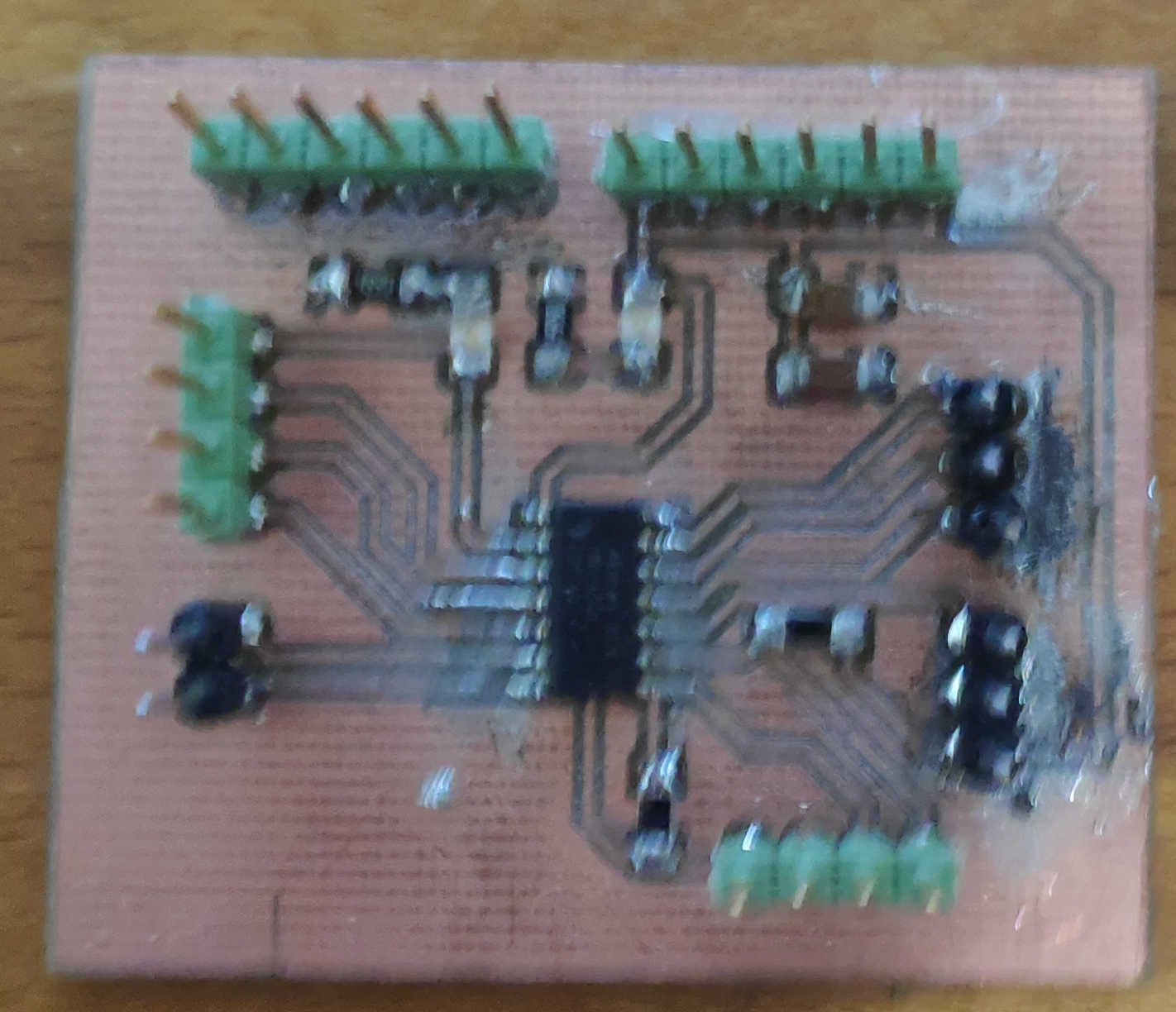
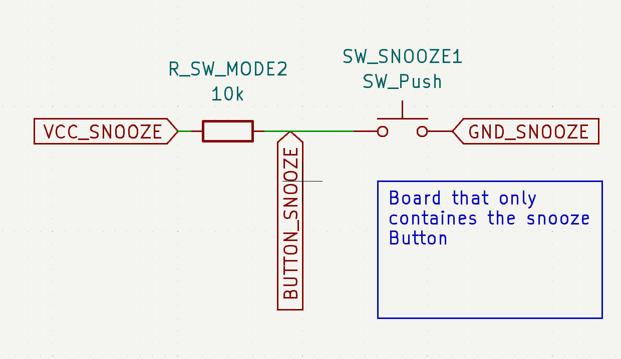
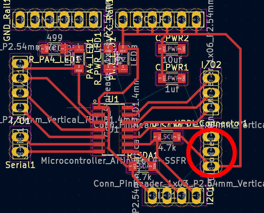
For the snooze button, I have created a simple pull-up button board design for an individual button. It has 2 buttons wired in parallel, which trigger the output when either is pressed. Both buttons are required for the large button head, as this makes it easier to push down. Connect this PCB signal to pin PA7/(3) and VCC and GND to PCB power and GND.
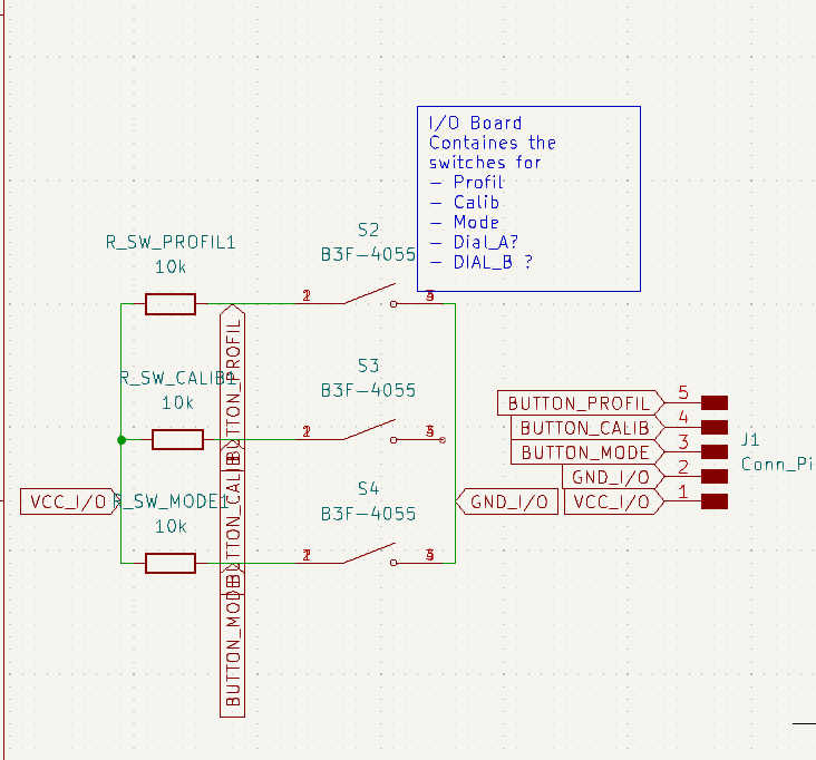
The other 3 buttons are equally spaced on the same PCB based on 3D model cut-out. Each button is driven as a pullup and is connected to its own pinhead. Each button is powered by the same VCC and GND pin. The VCC and GND pins are connected to the power and GND pins on the board, respectively. The data pins should be connected to pins PA1 - PA3 (8-10).

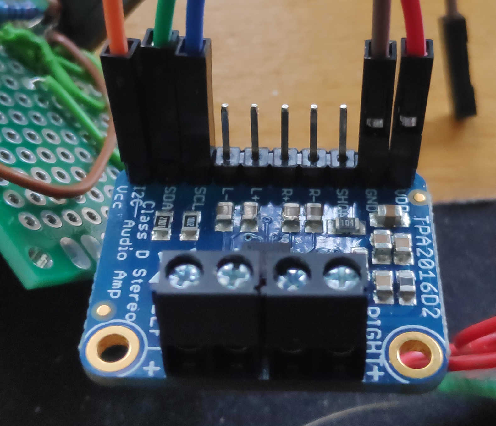
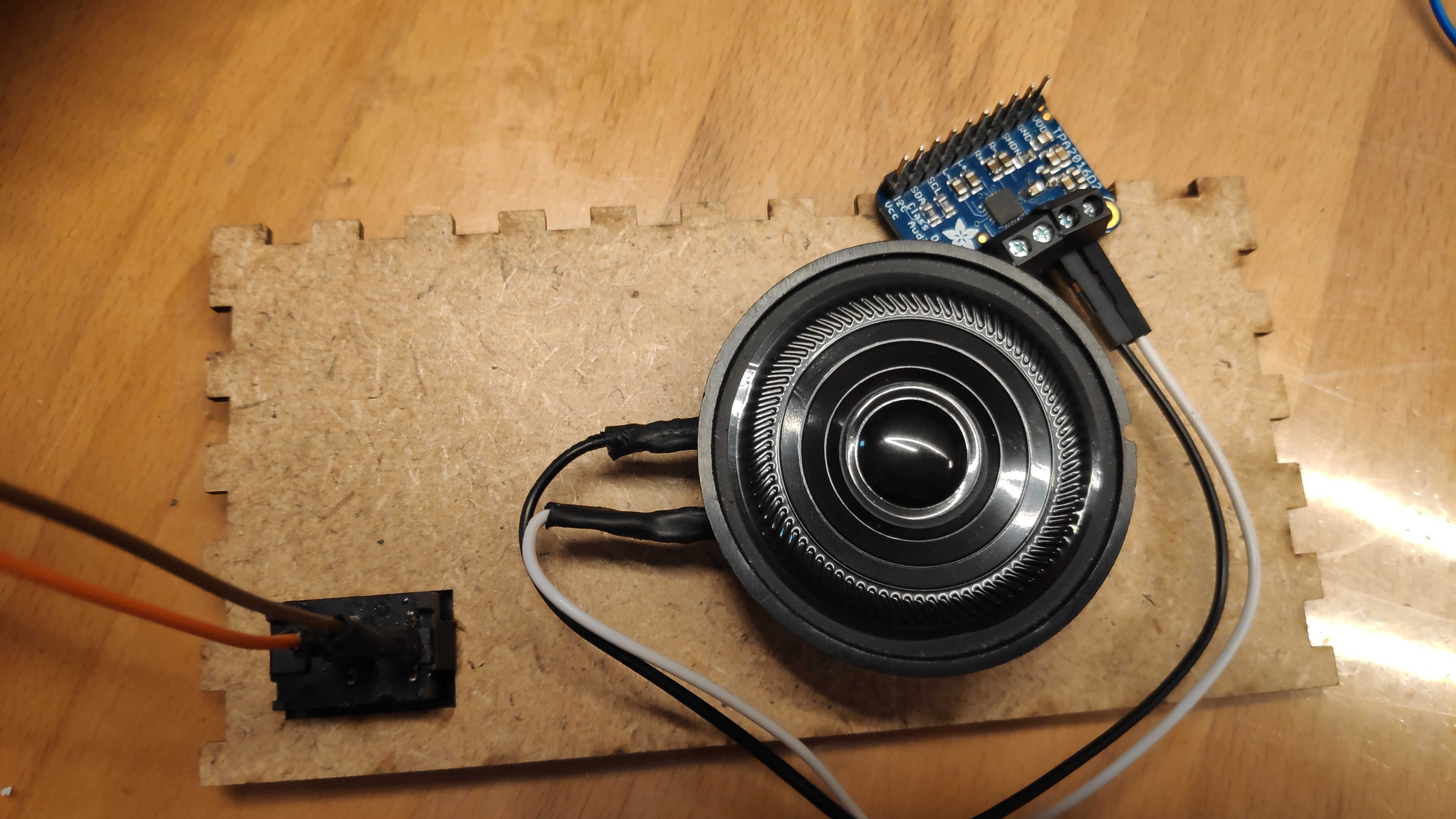
I used a pre-built breakout board for the amplifier board. This board should be connected to the loudspeakers. The loudspeaker pins should be screwed down and the loudspeaker cable should be fed through. I used one speaker connected to the right channel. The I2C vcc pin must be connected to the Vcc rail of the main PCB to set up the I2C pull-up resistor of this board. Connect the I2C SCL and SDA to the SCL and SDA of the main PCB. I used a 1 to 2 cable that allows the display to be connected later. To drive the speaker itself, connect the right channel + pin to the PA4 / (0) pin on the main PCB. Connect right channel - to the GND rail. Also connect VCC and GND to PCB Power and GND.
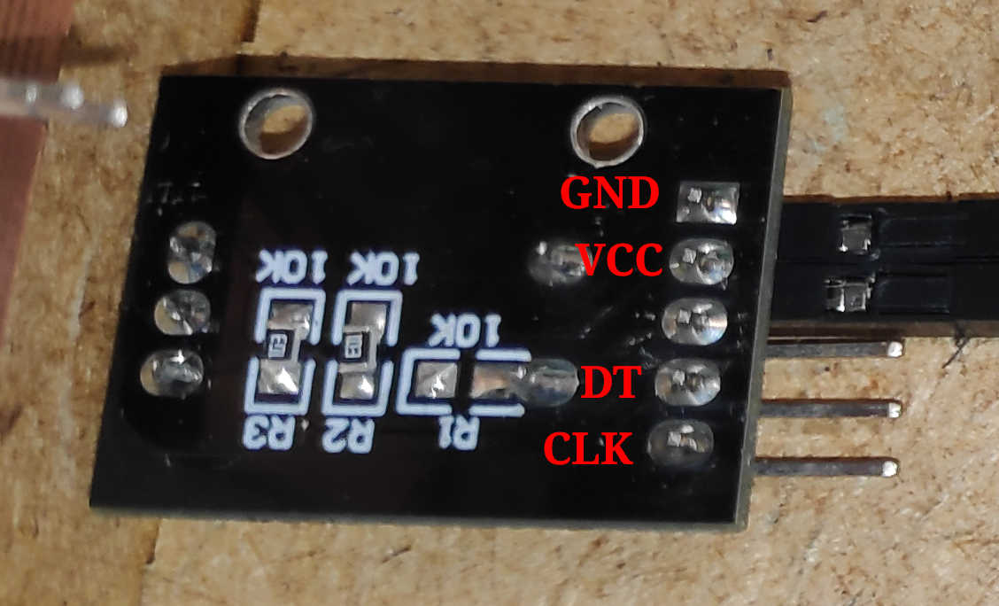
For the encoder I used a breakoutboard with 2 digital pins (CLK and DT), VCC and GND. The connection of CLK and DT determines the direction of the encoder. Attach PA5 (1) and PA6 (2) to CLK and DT pins. If you want to use an interrupt for better readings. Connect CLK to PA6. In the same way, connect VCC and GND to the corresponding rail on the PCB.
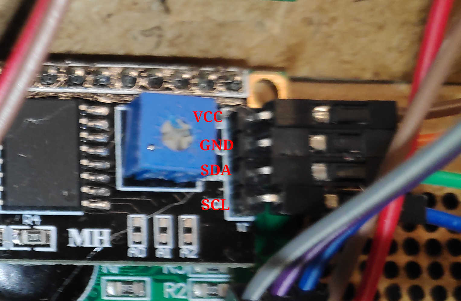
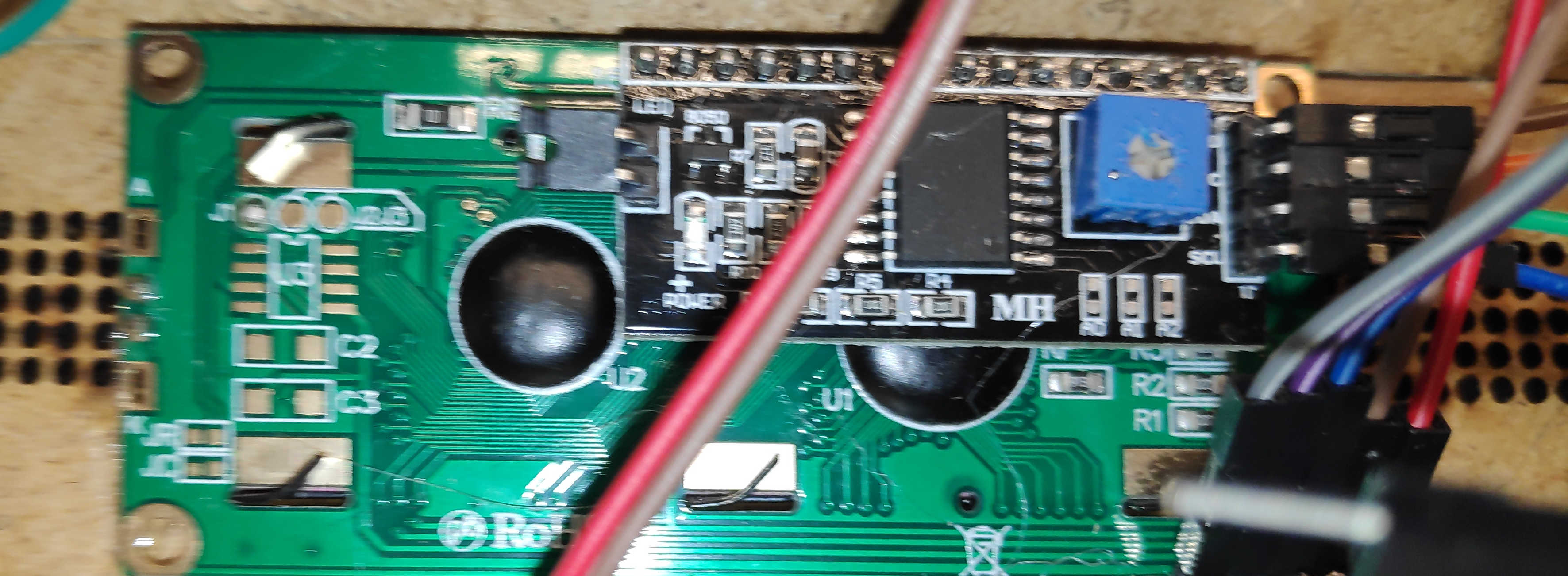
To show the current state use an I2C LCD. Especially for this ATTiny I recommend to use an LCD-Char display, because most pure pixel base displays have too big Arduino libraries to fit into the flash. This is also the reason why I switched to an LCD-Char in this step. Use an I2C connection to connect the LCD to the PCB. Connect VCC and GND to the power rail of the PCB or use the GND and VCC on the I2C rail.
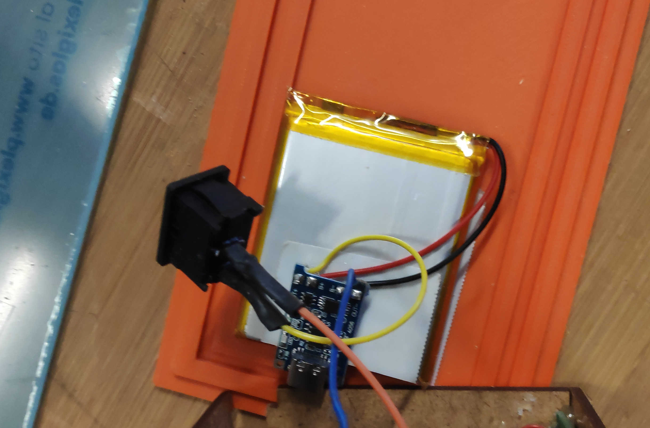
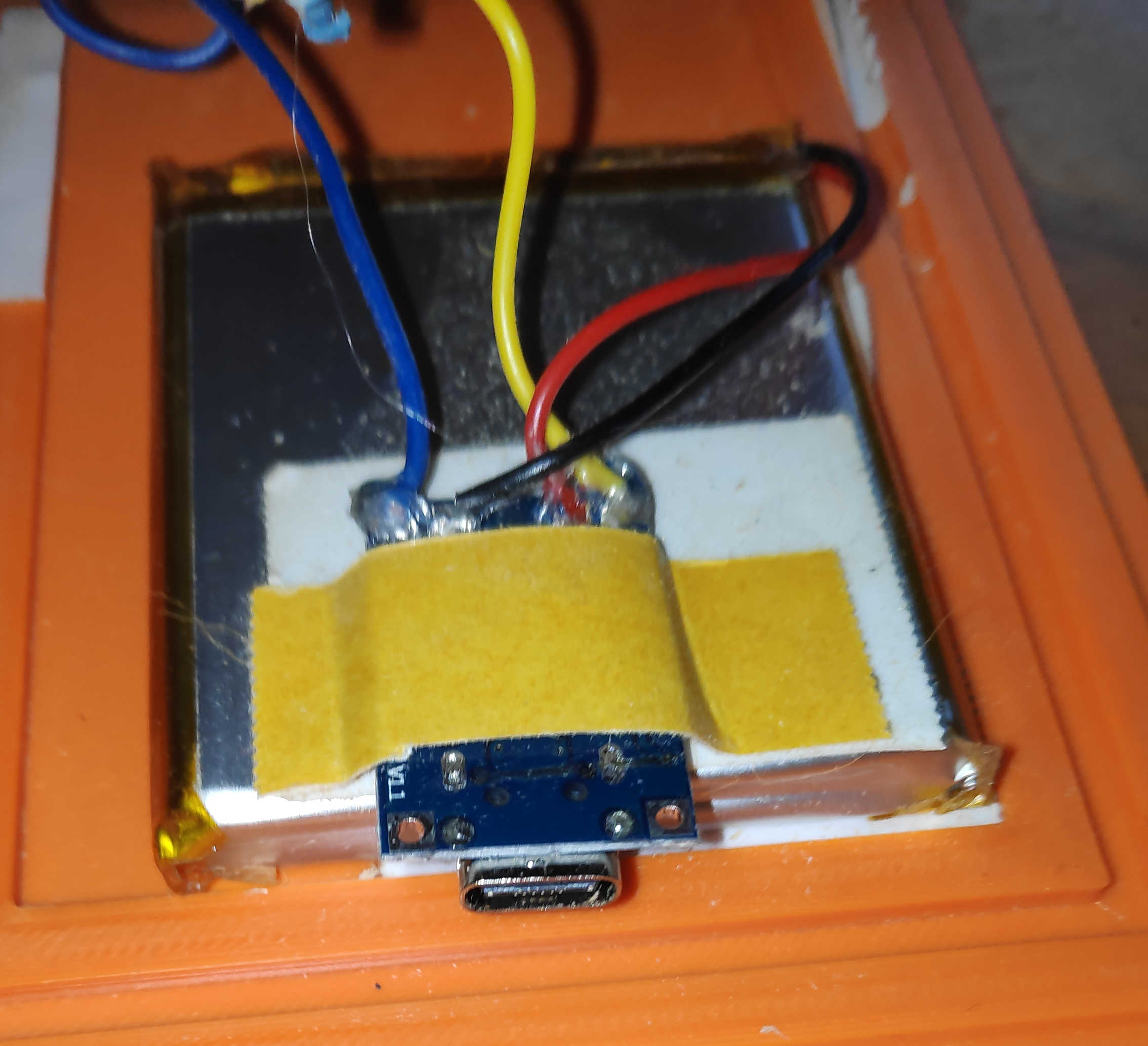
To power the clock without the programmer, a battery charger must be installed. Connect an accessible battery to the charger by soldering B+ to battery + and B- to battery -. Connect the off switch to the charger by soldering a switch cable to OUT+. Note that the off switch must first be inserted into the back panel and then soldered on. This will avoid some headache later on. Finally, solder a jumper wire to the OUT- of the charger module. Check if any cables were broken during the process. If not glue each cable on the charging module with a tiny bit of hot-glue.
Assamble
The best place to start the installation of the electronics into the box is the display itself. Remove the back of the box, if not already done, to access the inside. Add the Display by hot gluing around the Display frame and sticking the frame through the cut out. This will be enough to hold the display in place.
Next, glue the PCB with the 3 buttons to the front panel. If the distance between the buttons is correct, then the heads of the custom buttons should just stick out of the box. If the buttons get stuck when you press them down, then the whole buttons themselves should stick out as an alternative. Follow this up by pushing the rotary encoder through the wall and tightening the nut to secure it.

For the snooze button, follow the same procedure as for the other buttons. Use a piece of wood to fill in the air between the PCB and the top wooden plate if the button fits. Or use screws on each side to fix it. Glue the button in place with a little hot glue.
To fit the off switch to the box, simply push it through the cut-out in the back of the box. Most off-switches of this type have a built-in holding mechanism. This will snap into place when it is pushed into a cut-out of a similar size. Apply some glue to the switch if it won't stick to the wall.
For the right wall, glue the main PCB so there is space between the bottom and the wall. This makes connecting long wires from distant components easier than using the base-plate.
Attach the speaker to the back, leaving space between the main PCB, top button PCB and on/off switch. Wrap the speaker cable around the speaker and glue the amplifier board to the back panel.
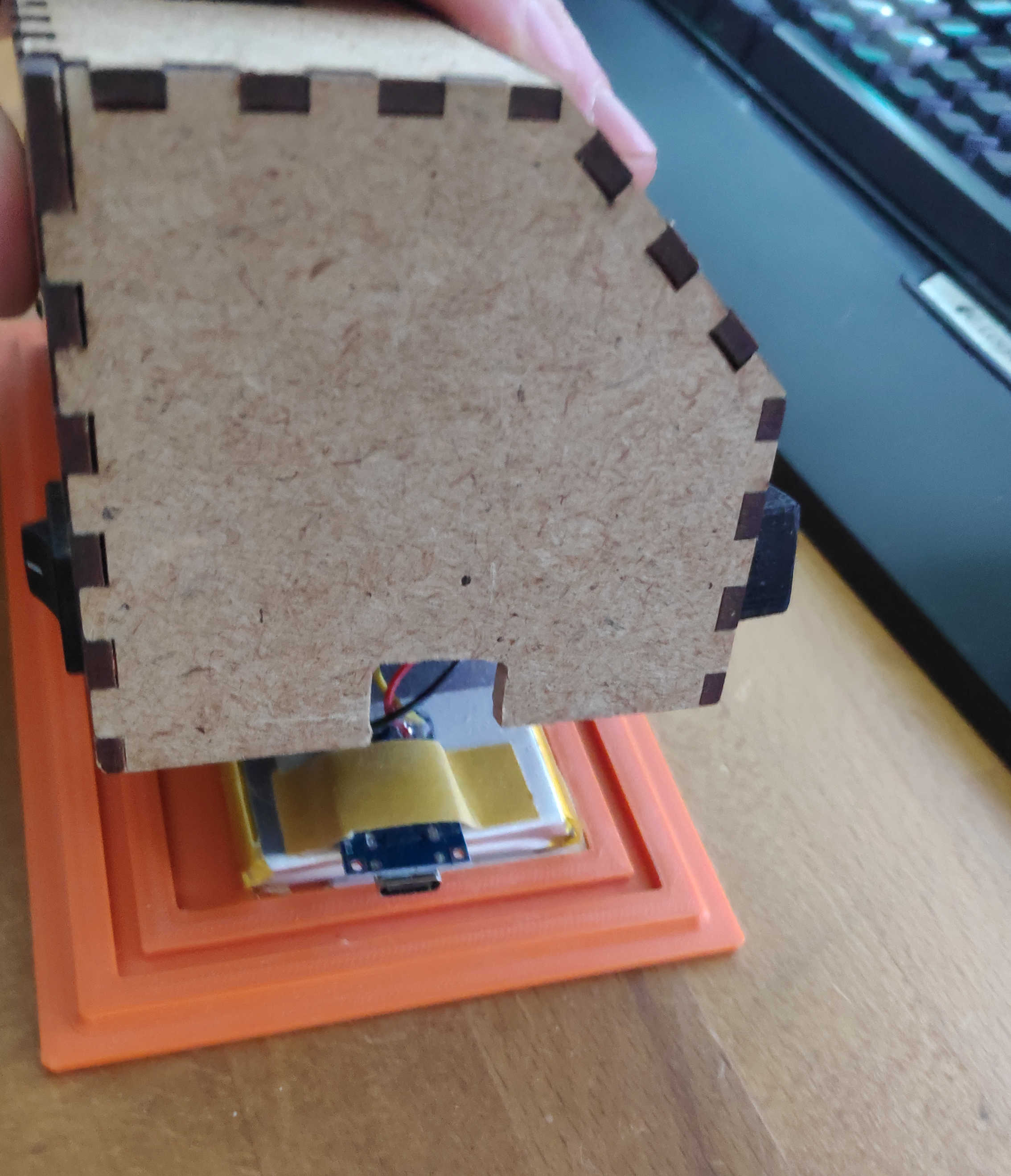
Finally, place the battery and charger on the bottom panel. Make sure they don't get blocked by other components. Use the back or left wall to access the charger connector. Secure the battery in place with tape or glue. Tape the battery cable to the top of the battery and glue the charger to the top of the battery against the wall. Depending on the size of the battery or the placement of the charger, you may need to adjust the 3D model for this part.
Program
The program itself consists of a few Arduino libraries, which I used to have easier control over the input and output devices. For I2C control I used the standard Wire library which is already configured for the Attiny when the megaTinyCore board manager is used. I used the Arduino library "Adafruit TPA2016" to control the amplifier over I2C. To control the encoder I used the “Rotary Encoder" library by Matthias Hertel. Finally, for the LC display, I used the "LiquidCrystal I2C" library by Frank de Brabander to control it via I2C. In order to get a specific pitch note tone, I used the example from the Arduino website called "toneMelody". This uses the standard Arduino library tone functions to play a sound. For the button, I modified the code from the "Button" library by Michael Adams https://github.com/madleech/Button to have fewer functions:
#include <Wire.h>
#include "Pitches.h"
#include <Adafruit_TPA2016.h> // Amplifier
#include <RotaryEncoder.h>
#include <LiquidCrystal_I2C.h>
Starting with the constants, I went on to define each of the pins that I wanted to use with the Attiny. In addition, I also defined the I2C address of the LCD display. I didn't need to define the address of the amplifier board, because the library I used already did that:
const int PIN_BTN_SNOOZE = 3 , PIN_BUTTON_MODE = 10, PIN_BUTTON_CALIB = 9, PIN_BTN_PROFIL = 8;
const int PIN_ENCODER_CLK = 2 , PIN_ENCODER_DT = 1; //1 , 2
const int PIN_SPEAKER = 0; // PA2
const int LCD_I2C_adress = 0x27 ; //0x20;
I created a button class to keep track of the button's state. It has few basic functions and can be initialised either pullup or pulldown depending on the real button configuration. I used a pull-up configuration for the button as described above. This button class has a read() function that checks the current button state and returns bool. This will update most of the flags on the button when called. This function is then used to determine if a button is currently being pressed. If this is the case, the state of the button can be checked using the press() function. This compares the read state with the active pull state of the button and returns a bool. If you want to check if the button has been pressed, call the pressed() function which compares the current read state with the pressed state and checks if it has changed. This function returns true only once during button press. The hasChanged() function checks if the flag set by read() has changed. If it has, set the chang flag to false and return true, as the change should only occur once. In case you want to change the pull state while using the function, I also added the setState() function to change the object's logical pull state.
#define button_refresh_intervall 100
class Button {
private:
unsigned long check_intervall = button_refresh_intervall;
unsigned long ignore_until_time;
bool state = HIGH; // Current State
bool m_hasChanged;
int m_PIN = 0 ;
bool PRESSED = LOW;
bool RELEASED = HIGH;
public:
Button ( int PIN)
: m_PIN ( PIN ) {
pinMode ( m_PIN, INPUT ) ;
}
enum PULL_STATE {
PULLUP = LOW,
PULLDOWN = HIGH
} ;
Button ( int PIN , Button::PULL_STATE pull_state)
: m_PIN ( PIN ) {
pinMode ( m_PIN, INPUT ) ;
setState ( pull_state ) ;
}
void setState ( bool pull_state) {
this -> PRESSED = pull_state;
this -> RELEASED = ! this -> PRESSED ;
}
bool press () {
// Compares against current State of Button
return this -> read () == this -> PRESSED ;
}
bool pressed () {
// Compares against current State of Button
return this -> read () == this -> PRESSED && this -> hasChanged () ;
}
// SET to Interrupt? //
bool read () {
// After past Countdown Read
bool afterUntil = ( ignore_until_time <= millis ()) ;
// And State has Changed
bool tmp_hasChanged = digitalRead ( m_PIN ) != state;
// Change State of Button
if ( afterUntil && tmp_hasChanged ) {
ignore_until_time = millis () + check_intervall;
state = !state;
m_hasChanged = true ;
}
// Return Current State => High or Low
return state;
}
bool hasChanged () {
// Makes sure that the CHECK only ACCURES one time after Check
if ( m_hasChanged ) {
m_hasChanged = false ;
return true ;
}
return false ;
}
};
Another class I wrote is Time, which is used to store time as an object. It does not change over time, for that you can use the Clock class. It stores the time in hours, minutes, seconds and milliseconds. It can be called as an empty constructor to set the time to 00:00:00 or with the exact time. Using the set function for each parameter, such as setHours(), allows the time object to be set to a given number. Each function uses the module operator to prevent time overflow. For example, setHours() is limited to a value between 0 and 23. A define for each max time unit can easily be used to set the limit. The add functions like addMinutes() are used to add a certain amount of time in their respective size. These functions calculate the new time to be set and call the next higher add function to add the overflow. For example, a 61 minute offset creates an overflow of about one hour, which calls the addHours() function. Each time unit can be read with the help of the getter function. Finally the toString() function returns an ordered time string.
// CLOCK Predefines //
#define max_hours 24
#define max_minutes 60
#define max_seconds 60
#define max_milliseconds 1000
...
class Time {
protected:
unsigned int m_hours = 0 ;
unsigned int m_minutes = 0 ;
unsigned int m_seconds = 0 ;
unsigned long m_milliseconds = 0 ;
public:
Time () {}
Time ( int hours , int minutes , int seconds)
: m_hours ( hours ) ,
m_minutes ( minutes ) ,
m_seconds ( seconds ) {
m_milliseconds = 0 ;
}
// Adder
void addMilliseconds ( unsigned long milliseconds) {
unsigned long tmp_milliseconds = this -> m_milliseconds + milliseconds;
if ( tmp_milliseconds >= max_milliseconds ) {
addSeconds (( int ) tmp_milliseconds / max_milliseconds ) ;
}
this -> m_milliseconds = tmp_milliseconds % max_milliseconds;
}
void addSeconds ( int seconds) {
int tmp_seconds = this -> m_seconds + seconds;
if ( tmp_seconds >= max_seconds ) {
addMinutes (( int ) tmp_seconds / max_seconds ) ;
}
this -> m_seconds = ( tmp_seconds ) % max_seconds;
}
void addMinutes ( int minutes) {
int tmp_minutes = (this -> m_minutes + minutes ) ;
if ( tmp_minutes >= max_minutes ) {
addHours (( int ) tmp_minutes / max_minutes ) ;
}
this -> m_minutes = tmp_minutes % max_minutes;
}
void addHours ( int hours) {
this -> m_hours = (this -> m_hours + hours ) % max_hours;
}
//SET
void setMilliseconds ( unsigned long milliseconds) {
this -> m_milliseconds = milliseconds % max_milliseconds;
}
void setSeconds ( unsigned int seconds) {
this -> m_seconds = ( seconds ) % max_seconds;
}
void setMinutes ( unsigned int minutes) {
this -> m_minutes = minutes % max_minutes;
}
void setHours ( unsigned int hours) {
this -> m_hours = hours % max_hours;
}
//GETTER
unsigned long milliseconds () {
return this -> m_milliseconds ;
}
unsigned int seconds () {
return this -> m_seconds ;
}
unsigned int minutes () {
return this -> m_minutes ;
}
unsigned int hours () {
return this -> m_hours ;
}
String toString () {
return ( String )this -> m_hours + ":" + this -> m_minutes + ":" + this -> m_seconds ;
}
};
The purpose of the Clock class is to keep track of the time and update it based on the system time. This class is an extension of the Time function and has updateLoop() as an additional function. Calling updateLoop() will update the time based on the offset from the last system time read to the currently set time. This will then set the clock time using addMilliseconds() using the offset to increase the time. This will only happen while the preventUpdate flag is not set. The flag prevents the clock from updating itself, but still stores the last system time update. Refreshing the time is necessary because after setting the flag back to false, this large offset would be added to addMilliseconds, which is not intended behaviour when calibrating the time.
class Clock : public Time {
unsigned long TIME = 0 ;
public:
bool preventUpdate = false ;
Clock ( int hours , int minutes , int seconds)
: Time ( hours, minutes, seconds ) {
TIME = millis () ;
}
void updateLoop () {
// Immer millis >= TIME
unsigned long offsetTime = millis () - TIME; // Diffrenz in ms
if ( !preventUpdate ){
addMilliseconds ( offsetTime ) ;
}
TIME = millis () ;
}
};
To store the time of an alarm, I've created the Profile class, which also extends the Time class. It stores the alarm time and plays it when the alarm time is reached. The isAlarm() function checks if a current alarm is active. This is done by calling refreshAlarm() which refreshes all flags for the alarm and returns the state. The refreshAlarm() function checks if the time of the alarm has passed and if it has, it sets the alarm flag to true. If a certain time has passed it automatically sets the flag to false and resets the alarm for the next day. The stopAlarm() can be used to manually disable an alarm. The restAlarm() function resets the alarm flags and mutes the speaker. To play the alarm, use the loopPlayAlarm() function, which plays one note per loop and keeps track of the current note being played. It uses setCurrentNote() to move to the next node and update any values needed. Finally, the setMinutes() and setHours() functions are overloaded. This is because the Profile class uses 2 Time objects to keep track of the start and end of the alarm. There is also an overload on the toString() function to just print out the hours and minutes.
class Profile : public Time {
// ALARM CHECK
/*
Alarm changed if
1. Stop Alarm
2. refress Alarm
- Alarm begin => true
- Alarm end => false
*/
bool _isAlarm = false ;
bool _alarmBeginnCalled = false ; //CALLED if ALARM TRIGGER WAS CALLED
//bool _alarmEndCalled = false; // CALLED IF ALARM CLOSED TRIGGER CALLED
int max_alarm_duration = 10 ; // in minutes
Time endTime;
/*
note durations: 4 = quarter note, 8 = eighth note, etc.:
to calculate the note duration, take one second divided by the note type.
e.g. quarter note = 1000 / 4, eighth note = 1000/8, etc.
int noteDuration = 1000 / noteDurations[thisNote];
*/
static const int melodyLength = 8 ;
int melody [melodyLength] = {
NOTE_FS6, NOTE_FS6, NOTE_FS6, NOTE_FS6, 0 , 0 , 0 , 0
} ;
int noteDurations [melodyLength] = {
16 , 16 , 16 , 16 , 16 , 16 , 16 , 16
} ;
public:
int currentNote = 0 ;
unsigned long currentMax = 0 ;
unsigned long after_time = 0 ;
bool noteChanged = true ;
bool _alarmClosed = false ;
// EMPTY
Profile () {}
Profile ( int hours , int minutes)
: Time ( hours, minutes, 0 ) {
endTime = Time (this -> m_hours , this -> m_minutes , 0 ) ;
endTime . addMinutes ( max_alarm_duration ) ;
}
bool isAlarm ( ::Clock & clock , Speaker & speaker) {
refreshAlarm ( clock, speaker ) ;
return _isAlarm;
}
void refreshAlarm ( ::Clock & clock , Speaker & speaker) {
bool alarmBegin = clock . hours () == this -> m_hours && clock . minutes () == this -> m_minutes ; // START TIME WINDOW (Note no Seconds) => Causes Many TRUE STATES
bool alarmEnd = clock . hours () == this -> endTime . hours () && clock . minutes () == this -> endTime . minutes () ; // END TIME WINDOW (Note no Seconds)=> Causes Many TRUE STATES
// Called Once
if ( alarmBegin && !_alarmBeginnCalled && !_alarmClosed ) {
_isAlarm = true ;
_alarmBeginnCalled = true ;
}
// Called in Loop
if ( alarmEnd ) {
_isAlarm = false ;
_alarmClosed = false ;
}
if ( !_isAlarm ) {
resetAlarm ( speaker ) ;
}
}
void stopAlarm () {
_alarmClosed = true ;
_isAlarm = false ;
}
// RESET ALL ALARM FLAGS
void resetAlarm ( Speaker & speaker) {
_isAlarm = false ;
_alarmBeginnCalled = false ; // FLAG to Prevent Double Calling beginn
setCurrentNote ( 0 ) ;
speaker . noTone () ;
}
void loopPlayAlarm ( Speaker & speaker) {
int noteDuration = 1000 / noteDurations [currentNote];
speaker . tone ( melody [currentNote], noteDuration ) ;
// to distinguish the notes, set a minimum time between them.
// the note's duration + 30% seems to work well:
int pauseBetweenNotes = noteDuration * 1.30 ;
delay ( pauseBetweenNotes ) ;
// stop the tone playing:
speaker . noTone () ;
setCurrentNote ( currentNote + 1 ) ;
}
void setCurrentNote ( int note) {
currentNote = note % melodyLength;
noteChanged = true ;
}
void setMinutes ( unsigned int minutes) {
this -> m_minutes = minutes % max_minutes;
// SET ENDTIMER //
this -> endTime . setMinutes ( minutes ) ;
this -> endTime . addMinutes ( max_alarm_duration ) ;
}
void setHours ( unsigned int hours) {
this -> m_hours = hours % max_hours;
// SET ENDTIMER //
this -> endTime . setHours ( hours ) ;
this -> endTime . addMinutes ( max_alarm_duration ) ;
}
String toString () {
return ( String )this -> m_hours + ":" + this -> m_minutes ;
}
};
For the speaker, I created a class that controls the speaker and the amplifier board. It uses the Adafruit_TPA2016 object from the same library to control the amplifier itself. Initialising the object sets the default settings for the amplifier board, such as gain, left-right channel, etc. It uses the standard tone() function, which can be called with speaker.tone() and the appropriate arguments, to play a tone with the speaker. The class also uses noTone(), which is used like the standard noTone(). Finally, setGain() is used to set the amplifier gain and getGain() to get the current gain state.
class Speaker {
private:
int m_PIN = 0 ;
int gain = - 5 ; // Default
bool rightchannel = true , leftchannel = false ;
Adafruit_TPA2016 audioamp; // Adress 0x58
public:
Speaker () {}
Speaker ( int PIN)
: m_PIN ( PIN ) {
audioamp = Adafruit_TPA2016 () ;
audioamp . begin () ;
audioamp . setGain ( gain ) ;
// Sets the Channel for the Speaker
audioamp . enableChannel ( rightchannel, leftchannel ) ;
//Limitsthe Speaker Overdrive
audioamp . setLimitLevelOn () ;
audioamp . setLimitLevel ( 25 ) ; // range from 0 (-6.5dBv) to 31 (9dBV)
audioamp . setAttackControl ( 5 ) ;
audioamp . setHoldControl ( 0 ) ;
audioamp . setReleaseControl ( 11 ) ;
}
void tone ( unsigned int frequency) {
:: tone ( m_PIN, frequency ) ;
}
void tone ( unsigned int frequency , unsigned long duration) {
:: tone ( m_PIN, frequency, duration ) ;
}
void noTone () {
:: noTone ( m_PIN ) ;
}
// MAX PEAK Loudness
// Takes in Gain as a value
void setGain ( int new_gain) {
// Mini//
if ( new_gain < - 28 ) {
new_gain = - 28 ;
}
// MAX //
if ( new_gain > 30 ) {
new_gain = 30 ;
}
gain = new_gain;
audioamp . setGain ( gain ) ;
}
int getGain () {
return gain;
}
};
Moving to the Setup() function, it initialises the I2C wires library and serial class. To ensure that the I2C is initialised before starting the speaker setup, it also initialises the speaker within the setup.
void setup () {
Wire . begin () ;
while ( !Serial ) { delay ( 10 ) ; }
Serial . begin ( 9600 ) ;
speaker = Speaker ( PIN_SPEAKER ) ;
lcd . init () ;
lcd . backlight () ;
}
The main loop is used to update all the values. These are the rotary encoder, which needs to be updated every tick with the .tick() function. Right after most of the updates, functions are called that are used to change the current state of the window display. This is done by checking if a button is pressed and the current display mode can be changed. These update functions are: UpdateStateProfile(), which checks if it can set the profile window. StateCali(), which checks if the state can be changed to calibration. UpdateMode() which updates the current clock mode on the display. And StateGain() which checks if the state can be changed to gain and sets the window to gain. The stateAlarm() function is used to check if a current alarm has been triggered and will override any window state without requiring permission.
void loop () {
stateAlarm () ;
updateStateProfil () ;
encoder . tick () ;
stateCali () ;
updateMode () ;
stateGain () ; //Encoder was MOVMET to set GAIN
encoder . tick () ;
…
}
The action() function, which is executed next in the loop, has a switch case statement for each window mode. This controls which current view to display and commands to execute. It has one statement for displaying Normal, Calibration, Alarm Profile, Gain and Alarm. Each statement uses show() to show it's state.
void loop () {
…
action ();
…
}
void {
encoder . tick () ;
switch ( window_status ) {
// Normal Updates
case window::_clock:
clock . preventUpdate = false ;
show ( "NORMAL" , setNormal ( modeIndex )) ;
break ;
// Calibration Updates
case window::_cali:
encoder . tick () ;
clock . preventUpdate = true ;
updateCali () ;
show ( "Calibration" , setClock ( caliModeIndex )) ;
break ;
// Profile Update
case window::_profil:
encoder . tick () ;
updateProfil () ;
show ( "SET PROFIL" , setProfil ( profileModeIndex, profile )) ;
break ;
// GAIN SET
case window::_gain:
encoder . tick () ;
show ( "GAIN" , ( String ) setGain () + "db" ) ;
break ;
// ALARM Active
case window::_alarm:
show ( "ALARM" , ( String ) "Its " + profile . toString ()) ;
profile . loopPlayAlarm ( speaker ) ;
break ;
}
}
The show() function calls the display object after a certain amount of time. This reduces flickering on the screen. This interval can be set manually by setting a different value for the "refreshtime" definition. When it's time to render a view, the whole display will be cleared and the current mode will be printed on the first line. The first line prints the mode as an argument via the function argument. The second line then prints out a value that is based on the current state. This value will also be given to the function.
void show (String mode, String text) {
Serial . println ( "------ Display --------" ) ;
Serial . println (( String ) "Profil State:" + mode ) ;
Serial . println (( String ) text ) ;
if ( display_until <= millis ()){
lcd . clear () ;
lcd . setCursor ( 0 , 0 ) ;
lcd . print (( String ) "State:" + mode ) ;
lcd . setCursor ( 0 , 1 ) ;
lcd . print (( String ) text ) ;
display_until = millis () + refreshtime;
}
}
The setNormal() function, used by the clock mode, is there to display the time and date based on the different states of the mode button. It uses a switch case statement of the mode to determine which one to return.
String setNormal ( int modeIndex) {
switch ( modeIndex ) {
case ::_time:
return ( String ) clock . toString () ;
break ;
case ::_date:
return ( String ) "2024-13-2" ;
break ;
case ::_datetime:
return ( String ) clock . toString () + " " + "13-2" ;
break ;
case ::_rotation:
// CHECK FOR TIME DELAY
if ( switch_until <= millis ()) {
switch_until = millis () + rotationIntervall;
rotationIndex++;
rotationIndex = rotationIndex % ( modeIndexMax - 1 ) ;
}
return setNormal ( rotationIndex ) ;
break ;
}
}
To calibrate the clock, I had to introduce a prevent update flag, so that the time is not updated during calibration. To calibrate the clock's time, call setClock() with the current index on what time unit it should calibrate and add the current encoder position change to the current selected time unit.
String setClock ( int & cal_mode) {
String text = clock . toString () ;
encoder . tick () ;
long newPos = encoder . getPosition () ;
if ( lastCali_Pos!=newPos ) {
long value = lastCali_Pos-newPos;
int tmp;
switch ( cal_mode ) {
case cali::_hour:
tmp = ((( clock . hours () + value ) %max_hours ) +max_hours ) %max_hours;
clock . setHours ( tmp ) ;
text = ( String ) "|" + clock . hours () + "|:" + clock . minutes () + ":" + clock . seconds () ;
break ;
case cali::_minute:
tmp = ((( clock . minutes () + value ) %max_minutes ) +max_minutes ) %max_minutes;
clock . setMinutes ( tmp ) ;
text = ( String ) clock . hours () + ":|" + clock . minutes () + "|:" + clock . seconds () ;
break ;
case cali::_seconds:
tmp = ((( clock . seconds () + value ) %max_seconds ) +max_seconds ) %max_seconds;
clock . setSeconds ( tmp ) ;
text = ( String ) clock . hours () + ":" + clock . minutes () + ":|" + clock . seconds () + "|" ;
break ;
}
lastCali_Pos = newPos;
}
return text;
}
Setting the alarm profile can be done in much the same way. The profile object itself is an extension of the time function, allowing it to set the time digits in the same way as the clock.
String setProfil ( int & cale_modeProfil, Profile & profile) {
String text = profile . toString () ;
long newPos = encoder . getPosition () ;
if ( lastProfil_Pos != newPos ) {
long value = lastProfil_Pos- newPos;
int tmp;
// SWITCH CASE based on CALI MODE//
switch ( cale_modeProfil ) {
case cali::_hour:
tmp = ((( profile . hours () + value ) %max_hours ) +max_hours ) %max_hours;
profile . setHours ( tmp ) ;
text = ( String ) "|" + profile . hours () + "|:" + profile . minutes () ;
break ;
case cali::_minute:
tmp = ((( profile . minutes () + value ) %max_minutes ) +max_minutes ) %max_minutes;
profile . setMinutes ( tmp ) ;
text = ( String ) profile . hours () + ":|" + profile . minutes () + "|" ;
break ;
}
profile . _alarmClosed = false ;
lastProfil_Pos = newPos;
}
return text;
}
To set the gain value use the getGain() loudspeaker and add the encoder offset to it. Then use setGain() and give it a new gain value.
String setGain (){
if ( hasChanged ()) {
int gain = speaker . getGain () + getEncoderOffset () ;
speaker . setGain ( gain ) ;
}
return ( String ) speaker . getGain () ;
}
The alarm is very basic. It simply displays the alarm text and uses the loopPlayAlarm() function of the alarm profile to loop to the alarm melodies.
…
profile . loopPlayAlarm ( speaker ) ;
...
Finally, if you want to bind the encoder update to an interrupt, remove any encoder.tick() statement and do the following:
void setup () {
...
attachInterrupt ( digitalPinToInterrupt ( PIN_ENCODER_CLK ) , updateEncoder, CHANGE ) ;
}
void updateEncoder (){
encoder . tick () ;
}
Or, if pin PA6(2) isn't available for interrupt calls, use as many encoder.tick() calls as possible for each loop. Note that the more times this function is called, the longer it will take to complete the loop. It's also recommended to call encoder.tick() before each encoder value reading for better results.
void loop () {
...
encoder . tick () ;
...
}
The full code is as follows:
#include <Wire.h>
#include "Pitches.h"
#include <Adafruit_TPA2016.h> // Amplifier
#include <RotaryEncoder.h>
#include <LiquidCrystal_I2C.h>
const int PIN_BTN_SNOOZE = 3 , PIN_BUTTON_MODE = 10, PIN_BUTTON_CALIB = 9, PIN_BTN_PROFIL = 8;
const int PIN_ENCODER_CLK = 2 , PIN_ENCODER_DT = 1; //1 , 2
const int PIN_SPEAKER = 0; // PA2
const int LCD_I2C_adress = 0x27 ; //0x20;
//const int SPEAKER_I2C_adress = 0x58; // Adress 0x58
//const int PIN_I2C_SDA = 6, PIN_I2C_SCL = 7;
// CLOCK Predefines //
#define max_hours 24
#define max_minutes 60
#define max_seconds 60
#define max_milliseconds 1000
// ENCODER last Position
int last_pos = 0;
//PROFILE CREATION //
int profileIndex = 0; // lengt+1 max
// CLOCK CALI //
bool cali_active = false ;
bool cali_press = false ;
int caliModeIndex = 0;
int profileModeIndex = 0 ;
#define profilerMax 3
#define accecptCounterMax 4 // COUNTER MAX of the ENUM
enum cali : int {
_hour = 0 ,
_minute = 1 ,
_seconds = 2 ,
_normal = 3 ,
};
// SET CURRENT WINDOW MODE //
enum window : int {
_clock = 0 ,
_cali = 1 ,
_profil = 2 ,
_alarm = 3 ,
_gain = 4 ,
};
// Encoder last Position for each Mode
long lastProfil_Pos = 0 ;
long lastCali_Pos = 0;
// DisplayTimer //
unsigned long display_until= 0 ;
#define refreshtime 500
// SHOW GAIN TIMER //
unsigned long show_gain_until = 0 ;
#define maxGainIntervall 1000
// SET CURRENT MODE OF NORMAL //
unsigned long switch_until = 0; // ROTATION COUNTER
int rotationIndex = 0; //Rotation INDEX
int modeIndex = 0;
#define modeIndexMax 4
#define rotationIntervall 1000
enum normal : int {
_time = 0 ,
_date = 1 ,
_datetime = 2 ,
_rotation = 3
};
// CHECK WEEK DAY //
enum weekday : int {
sunday = 1 ,
monday = 2 ,
tuesday = 3 ,
wednesday = 4 ,
thursday = 5 ,
friday = 6 ,
saturday = 7
};
window window_status = window::_clock; // CURRENT STATUS
// REFRESH INTERVALL //
#define button_refresh_intervall 100
class Button {
private:
unsigned long check_intervall = button_refresh_intervall;
unsigned long ignore_until_time;
bool state = HIGH; // Current State
bool m_hasChanged;
int m_PIN = 0 ;
bool PRESSED = LOW;
bool RELEASED = HIGH;
public:
Button ( int PIN)
: m_PIN ( PIN ) {
pinMode ( m_PIN, INPUT ) ;
}
enum PULL_STATE {
PULLUP = LOW,
PULLDOWN = HIGH
} ;
Button ( int PIN , Button::PULL_STATE pull_state)
: m_PIN ( PIN ) {
pinMode ( m_PIN, INPUT ) ;
setState ( pull_state ) ;
}
void setState ( bool pull_state) {
this -> PRESSED = pull_state;
this -> RELEASED = ! this -> PRESSED ;
}
bool press () {
// Compares against current State of Button
return this -> read () == this -> PRESSED ;
}
bool pressed () {
// Compares against current State of Button
return this -> read () == this -> PRESSED && this -> hasChanged () ;
}
// SET to Interrupt? //
bool read () {
// After past Countdown Read
bool afterUntil = ( ignore_until_time <= millis ()) ;
// And State has Changed
bool tmp_hasChanged = digitalRead ( m_PIN ) != state;
// Change State of Button
if ( afterUntil && tmp_hasChanged ) {
ignore_until_time = millis () + check_intervall;
state = !state;
m_hasChanged = true ;
}
// Return Current State => High or Low
return state;
}
bool hasChanged () {
// Makes sure that the CHECK only ACCURES one time after Check
if ( m_hasChanged ) {
m_hasChanged = false ;
return true ;
}
return false ;
}
};
class Time {
protected:
unsigned int m_hours = 0 ;
unsigned int m_minutes = 0 ;
unsigned int m_seconds = 0 ;
unsigned long m_milliseconds = 0 ;
public:
Time () {}
Time ( int hours , int minutes , int seconds)
: m_hours ( hours ) ,
m_minutes ( minutes ) ,
m_seconds ( seconds ) {
m_milliseconds = 0 ;
}
// Adder
void addMilliseconds ( unsigned long milliseconds) {
unsigned long tmp_milliseconds = this -> m_milliseconds + milliseconds;
if ( tmp_milliseconds >= max_milliseconds ) {
addSeconds (( int ) tmp_milliseconds / max_milliseconds ) ;
}
this -> m_milliseconds = tmp_milliseconds % max_milliseconds;
}
void addSeconds ( int seconds) {
int tmp_seconds = this -> m_seconds + seconds;
if ( tmp_seconds >= max_seconds ) {
addMinutes (( int ) tmp_seconds / max_seconds ) ;
}
this -> m_seconds = ( tmp_seconds ) % max_seconds;
}
void addMinutes ( int minutes) {
int tmp_minutes = (this -> m_minutes + minutes ) ;
if ( tmp_minutes >= max_minutes ) {
addHours (( int ) tmp_minutes / max_minutes ) ;
}
this -> m_minutes = tmp_minutes % max_minutes;
}
void addHours ( int hours) {
this -> m_hours = (this -> m_hours + hours ) % max_hours;
}
//SET
void setMilliseconds ( unsigned long milliseconds) {
this -> m_milliseconds = milliseconds % max_milliseconds;
}
void setSeconds ( unsigned int seconds) {
this -> m_seconds = ( seconds ) % max_seconds;
}
void setMinutes ( unsigned int minutes) {
this -> m_minutes = minutes % max_minutes;
}
void setHours ( unsigned int hours) {
this -> m_hours = hours % max_hours;
}
//GETTER
unsigned long milliseconds () {
return this -> m_milliseconds ;
}
unsigned int seconds () {
return this -> m_seconds ;
}
unsigned int minutes () {
return this -> m_minutes ;
}
unsigned int hours () {
return this -> m_hours ;
}
String toString () {
return ( String )this -> m_hours + ":" + this -> m_minutes + ":" + this -> m_seconds ;
}
};
class Clock : public Time {
unsigned long TIME = 0 ;
public:
bool preventUpdate = false ;
Clock ( int hours , int minutes , int seconds)
: Time ( hours, minutes, seconds ) {
TIME = millis () ;
}
void updateLoop () {
// Immer millis >= TIME
unsigned long offsetTime = millis () - TIME; // Diffrenz in ms
if ( !preventUpdate ){
addMilliseconds ( offsetTime ) ;
}
TIME = millis () ;
}
};
// TODO Extend with DB libary
class Speaker {
private:
int m_PIN = 0 ;
int gain = - 5 ; // Default
bool rightchannel = true , leftchannel = false ;
Adafruit_TPA2016 audioamp; // Adress 0x58
public:
Speaker () {}
Speaker ( int PIN)
: m_PIN ( PIN ) {
audioamp = Adafruit_TPA2016 () ;
audioamp . begin () ;
audioamp . setGain ( gain ) ;
// Sets the Channel for the Speaker
audioamp . enableChannel ( rightchannel, leftchannel ) ;
//Limitsthe Speaker Overdrive
audioamp . setLimitLevelOn () ;
audioamp . setLimitLevel ( 25 ) ; // range from 0 (-6.5dBv) to 31 (9dBV)
audioamp . setAttackControl ( 5 ) ;
audioamp . setHoldControl ( 0 ) ;
audioamp . setReleaseControl ( 11 ) ;
}
void tone ( unsigned int frequency) {
:: tone ( m_PIN, frequency ) ;
}
void tone ( unsigned int frequency , unsigned long duration) {
:: tone ( m_PIN, frequency, duration ) ;
}
void noTone () {
:: noTone ( m_PIN ) ;
}
// MAX PEAK Loudness
// Takes in Gain as a value
void setGain ( int new_gain) {
// Mini//
if ( new_gain < - 28 ) {
new_gain = - 28 ;
}
// MAX //
if ( new_gain > 30 ) {
new_gain = 30 ;
}
gain = new_gain;
audioamp . setGain ( gain ) ;
}
int getGain () {
return gain;
}
};
class Profile : public Time {
// ALARM CHECK
/*
Alarm changed if
1. Stop Alarm
2. refress Alarm
- Alarm begin => true
- Alarm end => false
*/
bool _isAlarm = false ;
bool _alarmBeginnCalled = false ; //CALLED if ALARM TRIGGER WAS CALLED
//bool _alarmEndCalled = false; // CALLED IF ALARM CLOSED TRIGGER CALLED
int max_alarm_duration = 10 ; // in minutes
Time endTime;
/*
note durations: 4 = quarter note, 8 = eighth note, etc.:
to calculate the note duration, take one second divided by the note type.
e.g. quarter note = 1000 / 4, eighth note = 1000/8, etc.
int noteDuration = 1000 / noteDurations[thisNote];
*/
static const int melodyLength = 8 ;
int melody [melodyLength] = {
NOTE_FS6, NOTE_FS6, NOTE_FS6, NOTE_FS6, 0 , 0 , 0 , 0
} ;
int noteDurations [melodyLength] = {
16 , 16 , 16 , 16 , 16 , 16 , 16 , 16
} ;
public:
int currentNote = 0 ;
unsigned long currentMax = 0 ;
unsigned long after_time = 0 ;
bool noteChanged = true ;
bool _alarmClosed = false ;
// EMPTY
Profile () {}
Profile ( int hours , int minutes)
: Time ( hours, minutes, 0 ) {
endTime = Time (this -> m_hours , this -> m_minutes , 0 ) ;
endTime . addMinutes ( max_alarm_duration ) ;
}
bool isAlarm ( ::Clock & clock , Speaker & speaker) {
refreshAlarm ( clock, speaker ) ;
return _isAlarm;
}
void refreshAlarm ( ::Clock & clock , Speaker & speaker) {
bool alarmBegin = clock . hours () == this -> m_hours && clock . minutes () == this -> m_minutes ; // START TIME WINDOW (Note no Seconds) => Causes Many TRUE STATES
bool alarmEnd = clock . hours () == this -> endTime . hours () && clock . minutes () == this -> endTime . minutes () ; // END TIME WINDOW (Note no Seconds)=> Causes Many TRUE STATES
// Called Once
if ( alarmBegin && !_alarmBeginnCalled && !_alarmClosed ) {
_isAlarm = true ;
_alarmBeginnCalled = true ;
}
// Called in Loop
if ( alarmEnd ) {
_isAlarm = false ;
_alarmClosed = false ;
}
if ( !_isAlarm ) {
resetAlarm ( speaker ) ;
}
}
void stopAlarm () {
_alarmClosed = true ;
_isAlarm = false ;
}
// RESET ALL ALARM FLAGS
void resetAlarm ( Speaker & speaker) {
_isAlarm = false ;
_alarmBeginnCalled = false ; // FLAG to Prevent Double Calling beginn
setCurrentNote ( 0 ) ;
speaker . noTone () ;
}
void loopPlayAlarm ( Speaker & speaker) {
int noteDuration = 1000 / noteDurations [currentNote];
speaker . tone ( melody [currentNote], noteDuration ) ;
// to distinguish the notes, set a minimum time between them.
// the note's duration + 30% seems to work well:
int pauseBetweenNotes = noteDuration * 1.30 ;
delay ( pauseBetweenNotes ) ;
// stop the tone playing:
speaker . noTone () ;
setCurrentNote ( currentNote + 1 ) ;
}
void setCurrentNote ( int note) {
currentNote = note % melodyLength;
noteChanged = true ;
}
void setMinutes ( unsigned int minutes) {
this -> m_minutes = minutes % max_minutes;
// SET ENDTIMER //
this -> endTime . setMinutes ( minutes ) ;
this -> endTime . addMinutes ( max_alarm_duration ) ;
}
void setHours ( unsigned int hours) {
this -> m_hours = hours % max_hours;
// SET ENDTIMER //
this -> endTime . setHours ( hours ) ;
this -> endTime . addMinutes ( max_alarm_duration ) ;
}
String toString () {
return ( String )this -> m_hours + ":" + this -> m_minutes ;
}
};
Speaker speaker;
Clock clock ( 22, 57, 50 );
RotaryEncoder encoder (PIN_ENCODER_CLK, PIN_ENCODER_DT, RotaryEncoder::LatchMode::TWO03); //FOUR3 // FOUR0 // TWO03
Button btn_snooze (PIN_BTN_SNOOZE, Button::PULL_STATE::PULLUP);
Button btn_cali (PIN_BUTTON_CALIB, Button::PULL_STATE::PULLUP);
Button btn_profil (PIN_BTN_PROFIL, Button::PULL_STATE::PULLUP);
Button btn_mode (PIN_BUTTON_MODE, Button::PULL_STATE::PULLUP);
//Adafruit_SSD1306 display(SCREEN_WIDTH, SCREEN_HEIGHT, &Wire, -1);
LiquidCrystal_I2C lcd (LCD_I2C_adress,16, 2 );
Profile profile ( 22, 58 );
void setup () {
Wire . begin () ;
while ( !Serial ) { delay ( 10 ) ; }
Serial . begin ( 9600 ) ;
speaker = Speaker ( PIN_SPEAKER ) ;
lcd . init () ;
lcd . backlight () ;
attachInterrupt ( digitalPinToInterrupt ( PIN_ENCODER_CLK ) , updateEncoder, CHANGE ) ;
}
void loop () {
// GENERAL ACTIONS //
//encoder.tick();
// REFRESH ACTION STATE //
stateAlarm () ;
updateStateProfil () ;
//encoder.tick();
stateCali () ;
updateMode () ;
stateGain () ; //Encoder was MOVMET to set GAIN
//encoder.tick();
// MAKES ACTION BASE ON MODE //
action () ;
clock . updateLoop () ;
//encoder.tick();
}
void action () {
//encoder.tick();
switch ( window_status ) {
// Normal Updates
case window::_clock:
clock . preventUpdate = false ;
show ( "NORMAL" , setNormal ( modeIndex )) ;
break ;
// Calibration Updates
case window::_cali:
//encoder.tick();
clock . preventUpdate = true ;
updateCali () ;
show ( "Calibration" , setClock ( caliModeIndex )) ;
break ;
// Profile Update
case window::_profil:
//encoder.tick();
updateProfil () ;
show ( "SET PROFIL" , setProfil ( profileModeIndex, profile )) ;
break ;
// GAIN SET
case window::_gain:
//encoder.tick();
show ( "GAIN" , ( String ) setGain () + "db" ) ;
break ;
// ALARM Active
case window::_alarm:
show ( "ALARM" , ( String ) "Its " + profile . toString ()) ;
profile . loopPlayAlarm ( speaker ) ;
break ;
}
}
// UPDATE ACTION STATE //
void stateCali () {
bool windowNotBussy = ( window_status == window::_clock ) || ( window_status == window::_cali ) ;
if ( windowNotBussy ) {
// MUST BE PRESSE, else it will Block other Button Request
if ( btn_cali . press () && !cali_active ) {
cali_active = true ;
cali_press = true ;
} else if ( ! btn_cali . press () &&cali_active ){
cali_press = false ;
}
if ( cali_active ) {
window_status = window::_cali;
}
if ( !cali_active ) {
window_status = window::_clock;
caliModeIndex = 0 ;
}
}
}
void stateProfil () {
bool windowNotBussy = ( window_status == window::_clock ) || ( window_status == window::_profil ) ;
if ( windowNotBussy ) {
if ( profileIndex >= 1 ) {
window_status = window::_profil;
} else {
window_status = window::_clock;
profileModeIndex = 0 ;
}
}
}
void stateGain () {
bool windowNotBussy = ( window_status == window::_clock ) || ( window_status == window::_gain ) ;
if ( windowNotBussy ) {
if ( hasChanged ()) {
window_status = window::_gain;
show_gain_until = millis () + maxGainIntervall;
}
if ( show_gain_until <= millis ()) {
window_status = window::_clock;
}
}
}
void stateAlarm () {
if ( profile . isAlarm ( clock, speaker )) {
window_status = window::_alarm;
}
if ( btn_snooze . press ()) {
window_status = window::_clock;
profile . stopAlarm () ;
}
}
// ALSO pos Passibil as Referenz
// CALC Offset since Last Call of Position
int getEncoderOffset () {
int newPos = encoder . getPosition () ;
// TEMP SAVE
int value = newPos - last_pos;
last_pos = newPos; // Reset Value
return value;
}
bool hasChanged () {
int newPos = encoder . getPosition () ;
return last_pos != newPos;
}
// UPDATE VALUE fur Cali //
void updateCali () {
if ( btn_cali . pressed () && !cali_press ) {
caliModeIndex++;
caliModeIndex = caliModeIndex % accecptCounterMax;
}
if ( caliModeIndex == cali::_normal ) {
cali_active = false ;
}
}
// UPDATE VALUE fur Profil //
void updateProfil () {
if ( btn_cali . pressed ()) {
profileModeIndex++;
profileModeIndex = profileModeIndex % profilerMax;
}
}
void updateStateProfil () {
if ( btn_profil . pressed ()) {
profileIndex++;
profileIndex = profileIndex % 2 ; //(profiles.length + 1);
}
stateProfil () ;
}
void updateMode () {
if ( btn_mode . pressed ()) {
modeIndex++;
modeIndex = modeIndex % modeIndexMax;
}
}
// SET VALUES //
String setNormal ( int modeIndex) {
switch ( modeIndex ) {
case ::_time:
return ( String ) clock . toString () ;
break ;
case ::_date:
return ( String ) "2024-13-2" ;
break ;
case ::_datetime:
return ( String ) clock . toString () + " " + "13-2" ;
break ;
case ::_rotation:
// CHECK FOR TIME DELAY
if ( switch_until <= millis ()) {
switch_until = millis () + rotationIntervall;
rotationIndex++;
rotationIndex = rotationIndex % ( modeIndexMax - 1 ) ;
}
return setNormal ( rotationIndex ) ;
break ;
}
}
String setGain (){
if ( hasChanged ()) {
int gain = speaker . getGain () + getEncoderOffset () ;
speaker . setGain ( gain ) ;
}
return ( String ) speaker . getGain () ;
}
String setProfil ( int & cale_modeProfil, Profile & profile) {
String text = profile . toString () ;
long newPos = encoder . getPosition () ;
if ( lastProfil_Pos != newPos ) {
long value = lastProfil_Pos- newPos;
int tmp;
// SWITCH CASE based on CALI MODE//
switch ( cale_modeProfil ) {
case cali::_hour:
tmp = ((( profile . hours () + value ) %max_hours ) +max_hours ) %max_hours;
profile . setHours ( tmp ) ;
text = ( String ) "|" + profile . hours () + "|:" + profile . minutes () ;
break ;
case cali::_minute:
tmp = ((( profile . minutes () + value ) %max_minutes ) +max_minutes ) %max_minutes;
profile . setMinutes ( tmp ) ;
text = ( String ) profile . hours () + ":|" + profile . minutes () + "|" ;
break ;
}
profile . _alarmClosed = false ;
lastProfil_Pos = newPos;
}
return text;
}
void updateEncoder (){
encoder . tick () ;
}
void show (String mode, String text) {
Serial . println ( "------ Display --------" ) ;
Serial . println (( String ) "Profil State:" + mode ) ;
Serial . println (( String ) text ) ;
if ( display_until <= millis ()){
lcd . clear () ;
lcd . setCursor ( 0 , 0 ) ;
lcd . print (( String ) "State:" + mode ) ;
lcd . setCursor ( 0 , 1 ) ;
lcd . print (( String ) text ) ;
display_until = millis () + refreshtime;
}
}
String setClock ( int & cal_mode) {
String text = clock . toString () ;
//encoder.tick();
long newPos = encoder . getPosition () ;
if ( lastCali_Pos!=newPos ) {
long value = lastCali_Pos-newPos;
int tmp;
switch ( cal_mode ) {
case cali::_hour:
tmp = ((( clock . hours () + value ) %max_hours ) +max_hours ) %max_hours;
clock . setHours ( tmp ) ;
text = ( String ) "|" + clock . hours () + "|:" + clock . minutes () + ":" + clock . seconds () ;
break ;
case cali::_minute:
tmp = ((( clock . minutes () + value ) %max_minutes ) +max_minutes ) %max_minutes;
clock . setMinutes ( tmp ) ;
text = ( String ) clock . hours () + ":|" + clock . minutes () + "|:" + clock . seconds () ;
break ;
case cali::_seconds:
tmp = ((( clock . seconds () + value ) %max_seconds ) +max_seconds ) %max_seconds;
clock . setSeconds ( tmp ) ;
text = ( String ) clock . hours () + ":" + clock . minutes () + ":|" + clock . seconds () + "|" ;
break ;
}
lastCali_Pos = newPos;
}
return text;
}
Flashing the board
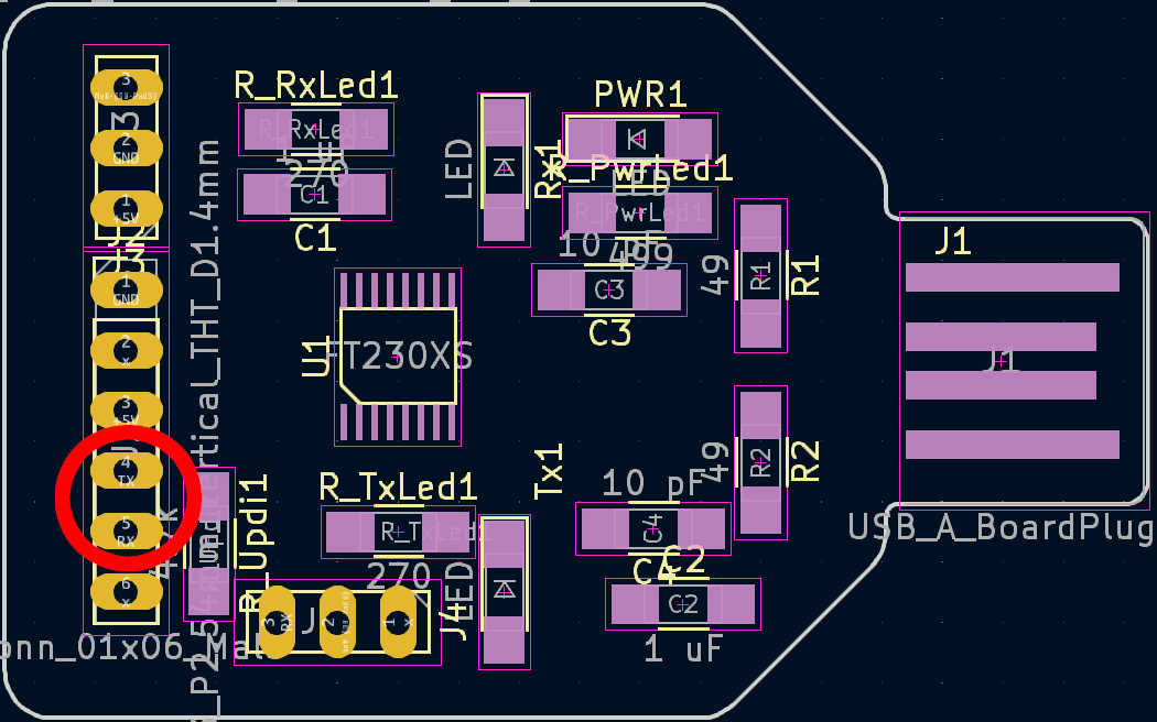
Finally, to upload the entire programme to the Attiny1614 or chip of your choice, connect it via UPDI or USB if possible. I used the Attiny1614, so I had to use the UPDI pin to flash the program to it. I used the programming board I made in week 8. Connect the VCC, GND and UPDI pins to the same pins on the main board.
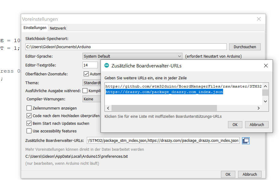
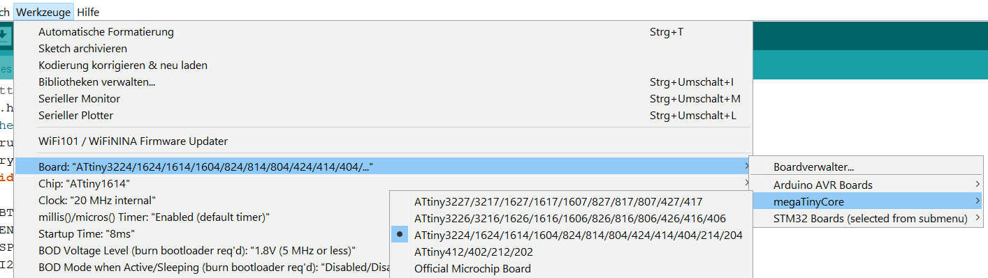
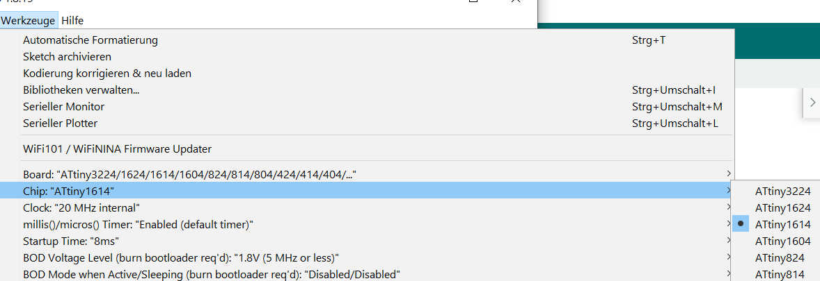
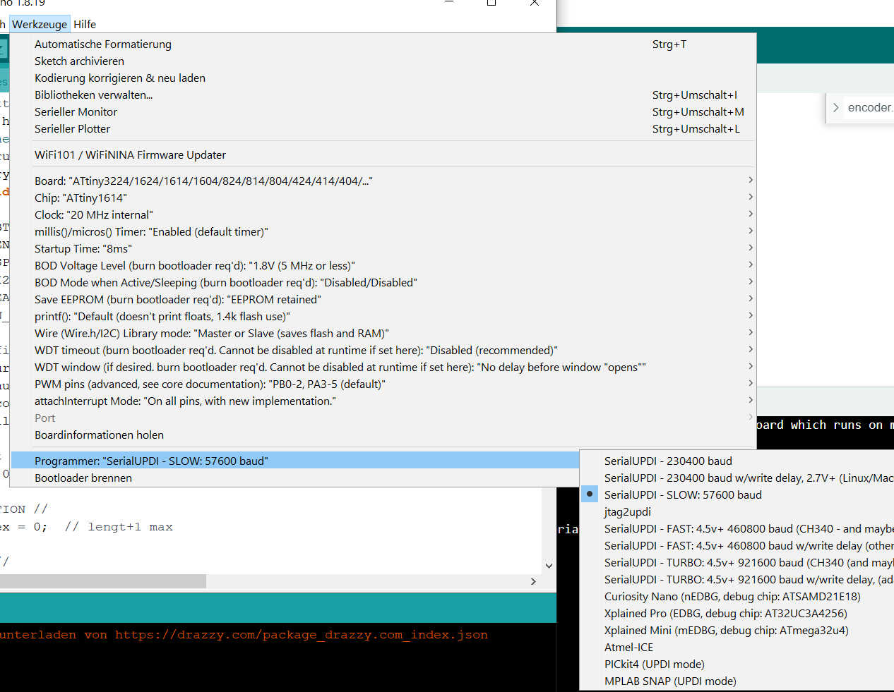
To upload the program from the Arduino IDE using UPDI, you need to set up the board and programming type. Open the Arduino IDE version 1 and open the sketch. Select Tools > Board > megaTinyCore. Select the ATtiny3324/1614 ... series. If you don't see the library, you'll have to add it manually using the options under file > settings. Add "https://drazzy.com/package_drazzy.com_index.json" to the board's URL. Next, set the chip by selecting ATtiny1614. Set the programmer to "SerialUPDI 57600 Baud". Finally, connect the programmer and select the new port that appears. Everything is now set up for uploading. The program can be uploaded by simply pressing the Arduino Upload button.
For debugging purposes, the serial port can be connected after upload. Simply connect the RX programmer to the TX main PCB and the TX to the RX main PCB.

When everything is uploaded, disconnect the programmer and reconnect the battery using the power switch. Connect the switch - to GND and the battery charger to VCC. The bottom can now be glued to the box for a permanent seal.
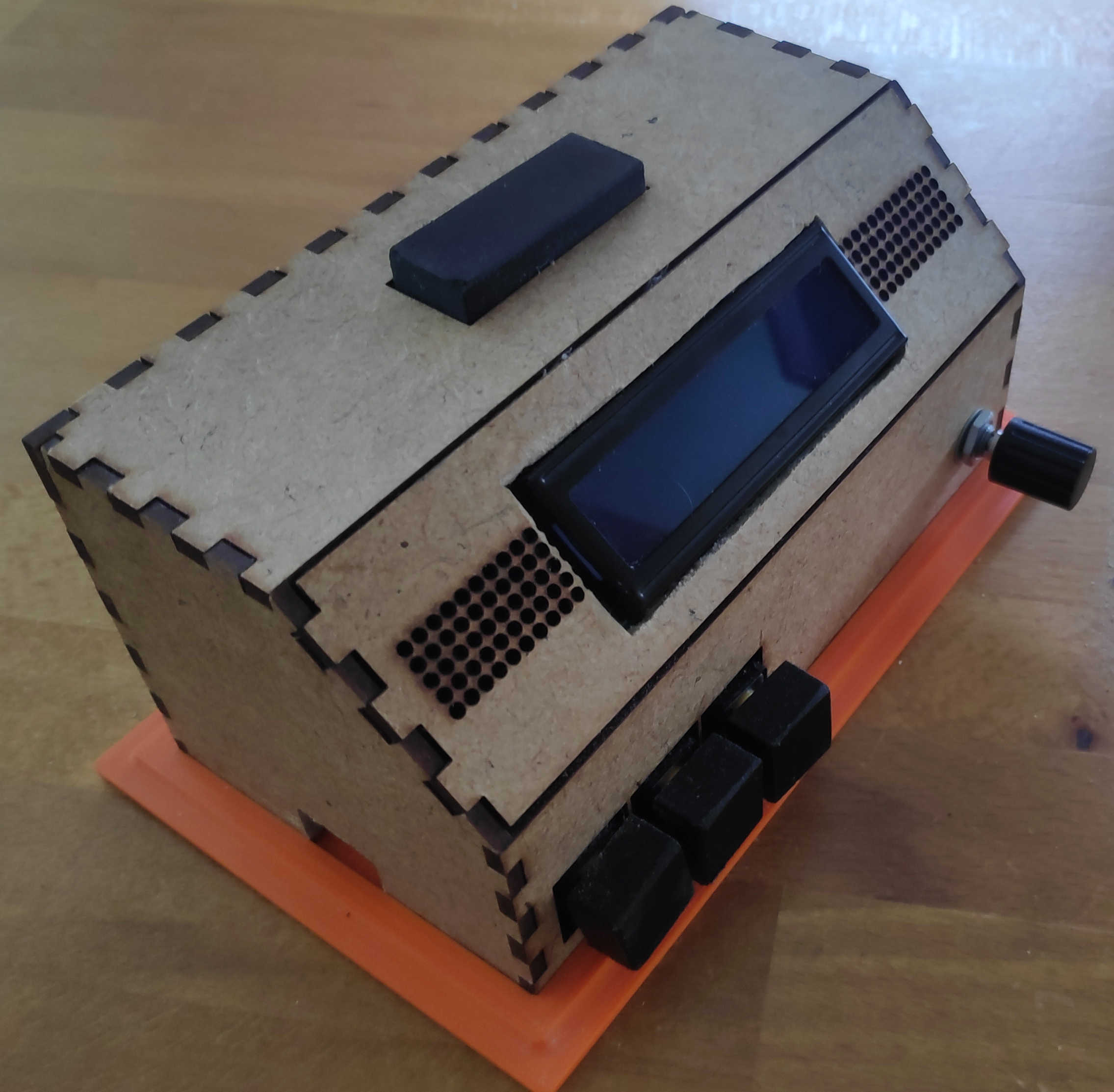
The final alarm clock should work like this:
Possible Upgrades
In the future, this clock could be extended to store more alarm profiles by creating a class to keep track of them. The time class could also be extended to keep track of the date and allow the clock to update it. The alarm profiles could then be set to go off when a certain date or day is reached. The clock could also be upgraded to an OLED display. This would require replacing the main PCB to gain more memory. All in all, this idea could still be expanded.
Recommended materials:
- Box: 3mm MDF-Board
- Button Head and Bottom Plate: PETG
- Amplifer-Board: Stereo 2.8W Class D Audio Amplifier - I2C
- Speaker: 8 ohm miniature speaker
- Rotary Encoder: KY-040-Rotary Encoder
- Buttons: 5 x B3F-4055
- Battery: Lithium Battery 3.7v
- Charging-Module: Type-c USB Lithium Battery Charger Module
- Display: 16 x 2 LCD-Char
- On/off switch:
- Perforated circuit board PCB
- Ceramic Resistor: 4 x 10k Ohm
- A bunch of Cables + Jumper Cable
- A few Pin Headers
- main-Chip: Instruction
- Programmer Board:Instruction
Here are the following files used: