Week 7 – Input/output Devices
For this week task was to create a circuit with 2 Input and 2 output devices. For the Input devices the limit was, that one should be an analog device and the other a digital device. As for the 2 Output devices, it was only allowed to use at maximum one LED and one device should be controlled by an imported library.
So I decied on using a servo motor and a LCD line Display as my output devices. As input devices I used a button for a digital signal and potentiometer as an analog device.
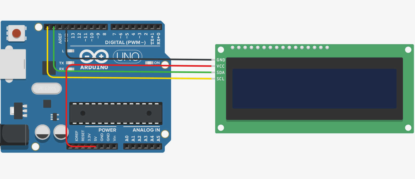
Today LCD displays using I2C connection to transfer signals. This creates a 4 Pin configuration, where the first to pins are just power (VCC) and GND. Connecting both respectly to the arduino power 5V and GND, gives the display power. The special I2C connection are SCL (Serial Clock) and SDA (Serial Data), which are connected to the arduino marked I2C SDA and SCL pins. In this case the arduino uno has only one Pin for each SCL (D19) and SDA (D18).https://docs.arduino.cc/hardware/uno-rev3
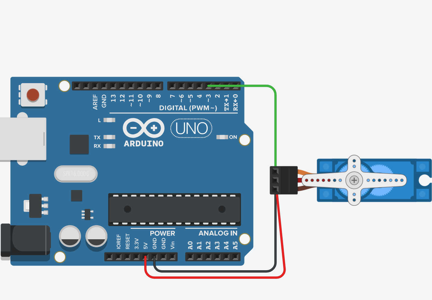
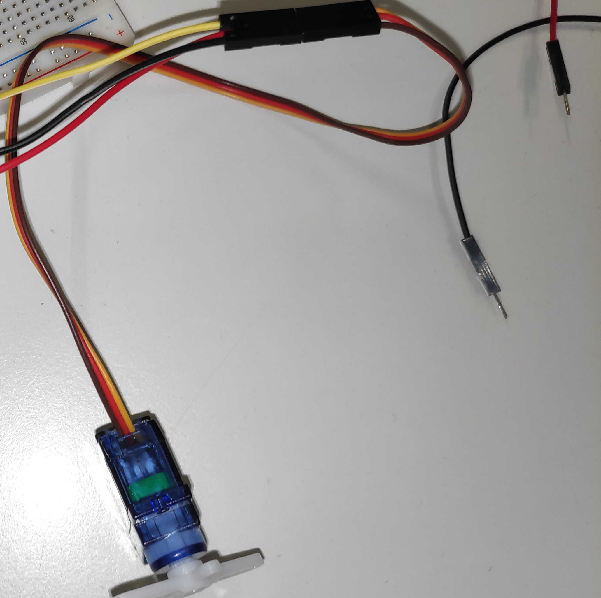
Next up is the servo motor, which uses 3 pins. Connect Arduino’s GND to GND and Arduino’s 5V to VCC. The third pin is the signal pin, which is connected to a pwm Pin. In this case it is D3 pin, which lets the servo gets controlled over a pwm signal.
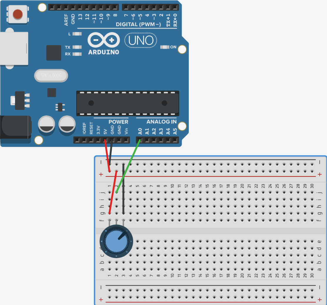
To connect the potentiometer, the outer pins to the left and right of the 3 pins are used as GND and VCC. The middle pin is connected to the analogue-in pin A0 of the Arduino. This sensor works like a variable resistor that changes its resistance depending on how far it is turned. This changes the voltage in a range between 0 and 5V, which generates an analogue signal. Normally a variabil resistor on its ownen would cause a short circuit, but the potentiometer already has another resistor built-in.
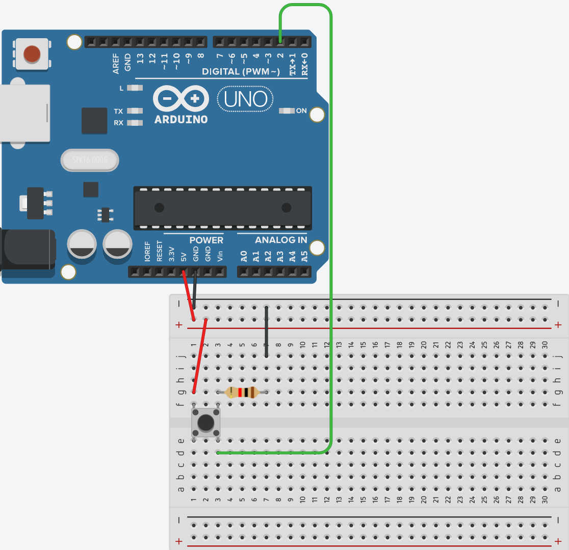
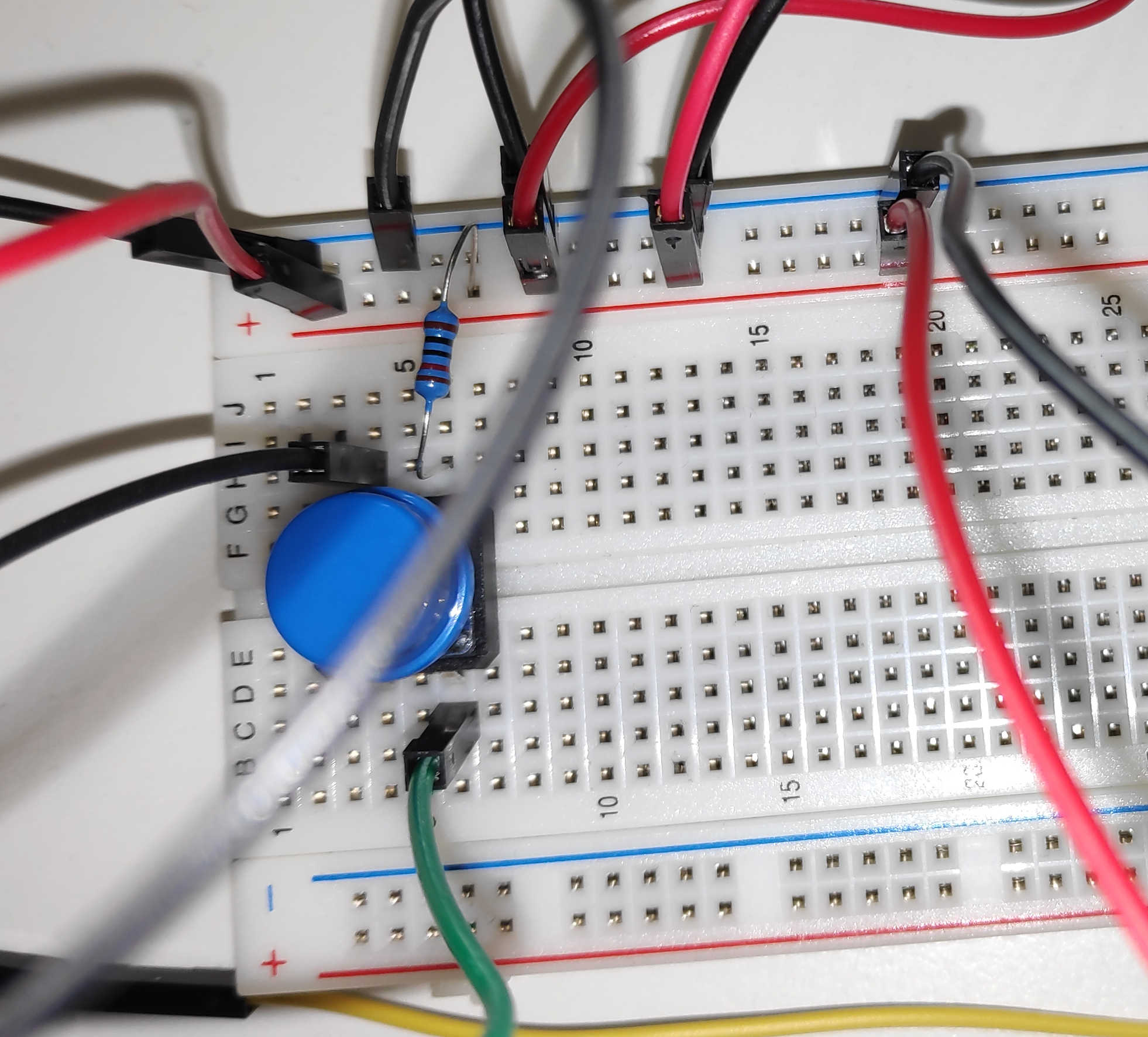
Lastly the button needs to be connected. As descried last week the button needs to be connected to VCC and GND. I used the pull down configuration for this button, because I wanted my signal to be on an active HIGH. So the resistor and input-pin needs to be placed at the GND to ensure a signal without interference.
Putting it all together, it should look like this:
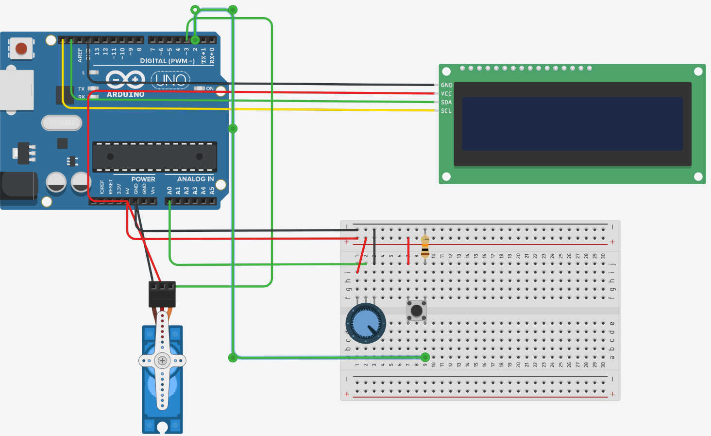
For the actually functioning of the code I decided, that the potentiometer should be used to set the position of the servo motor. Turning the Potentiometer should be than rotate the servo motor to position between min 0 °deg and max 180°deg. The button interacts with the display and simply displays a message on the display, when its being pressed.
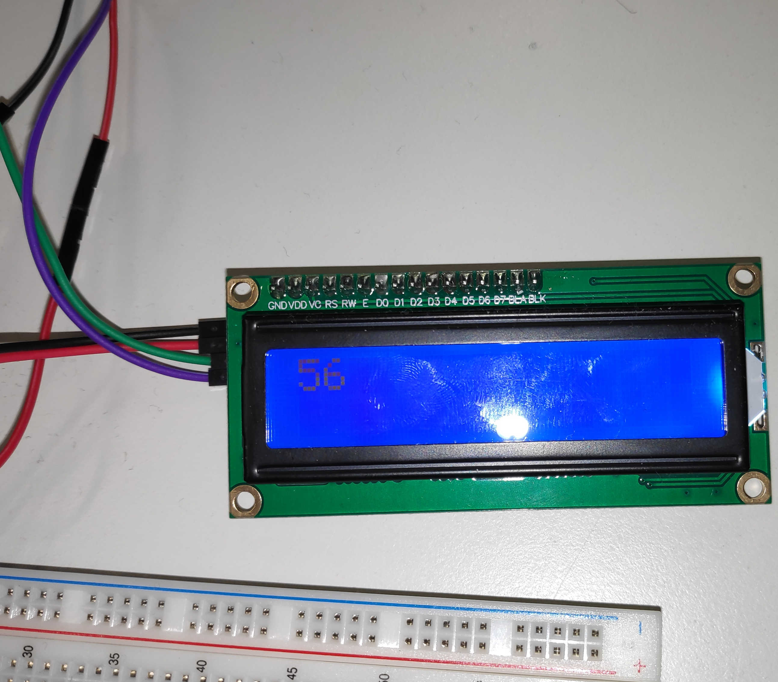
For the setup I first imported the need library “Servo” for the servo motor and “liquid Crystal I2C” for the display I2C interaction. As always I created a variables for each used pin to store the address. The analog and the digital pin for Potentiometer and Button are setup as Input with the normal pin mode. Different to the other pin setups the LCD Display needs to store a I2C address, because in I2C many device gets connected via “one Pin”. Therefore an address is needed to identify each device. The included Library initalisert the LCD-Display as an object, which need the arguments Address, Character Length and lines passed. The LCD exist as an object now, but it still needs to be initialized for the connection and the display has to be turned on manually. To print out a start message on the display, first the cursor position needs to be set. The cursor function takes in a char and a linen to define the writing start position. Than the print function can be used to display the text, by giving it the text.
                #include <LiquidCrystal_I2C.h>

                int BUTTON_pin = 2;
                int POTENTIOMETER_pin = A0;
                int LCD_I2C_adress = 0x20;

                LiquidCrystal_I2C lcd(LCD_I2C_adress,16,2);
                ...

                void setup()
                {
                    ...
                  lcd.init();
                  lcd.backlight();
                  lcd.setCursor(3,1);// 3 => Char 3 ; 1 => Linen
                  lcd.print("Starting up");

                  //BUTTON
                  pinMode(BUTTON_pin,INPUT);

                  //POTENTIOMETER
                  pinMode(POTENTIOMETER_pin, INPUT);

                  Serial.begin(9600);
                }
To setup the servo motor with its library, it also need to be created as an object. Using the Attach function from the object, it takes in the arguments Pin, Min. pulse and Max. pulse. Both min and max represent the pulse needed to turn the Servo in max. in min. direction, which is than represented by a PWM signal. Using “servo.write(0)” in the setup will setup the motors position at 0°deg.
                    #include <Servo.h>

                    ...
                    int SERVO_pin = 3;
                    Servo servo;

                    void setup()
                    {
                      servo.attach(SERVO_pin, 500, 2500);
                      servo.write(0);
                        ...
                    }
Entering the “loop call” the button program is written as one week before. The if statement checks if the button reads a high value, which indicates that the button was pressed. If the statement is true the function “setDisplayButton” will be executed. This will clear the whole LCD screen and write at the bottom line of the screen “Button pressed”. If the statement is false it will execute the function “setDisplayPotentiometer”. This will clear the LCD display and print at the top line the current position of the servo motor in deg.
                void loop()
                {
                    ...
                    // Button //
                    bool BUTTON_status = (HIGH == digitalRead(BUTTON_pin));
                    if(BUTTON_status){
                        setDisplayButton();
                        delay(100);
                    }else{
                        setDisplayPotentiometer(deg);
                    }
                }

                ...

                void setDisplayButton(){
                    lcd.clear();
                    lcd.setCursor(0,1);
                    lcd.print("Button pressed");
                    Serial.println("Button Was Pressed");
                }

                void setDisplayPotentiometer(int &value){
                    lcd.clear();
                    lcd.setCursor(0,0);
                    lcd.print(value);
                    Serial.println(value);
                }
To read in the potentiometer at the loop, I used analogRead(). This will return a value between 0 to 1023, which represent the current applied voltage. Using a map function this value can be than mapped between 0° and 180° deg. Using the “setMotorPosition()” and passing the degree as the position, a write function on the motor will be executed setting the motor position.
                void loop()
                {
                  // Servo //
                  // ANALOG READ
                  int deg = map(analogRead(POTENTIOMETER_pin), 0,1023, 0, 180);
                  // WRITE SERVO
                  setMotorPosition(deg);

                  ...
                }

                ...

                void setMotorPosition(const int °){
                    servo.write(deg);
                }
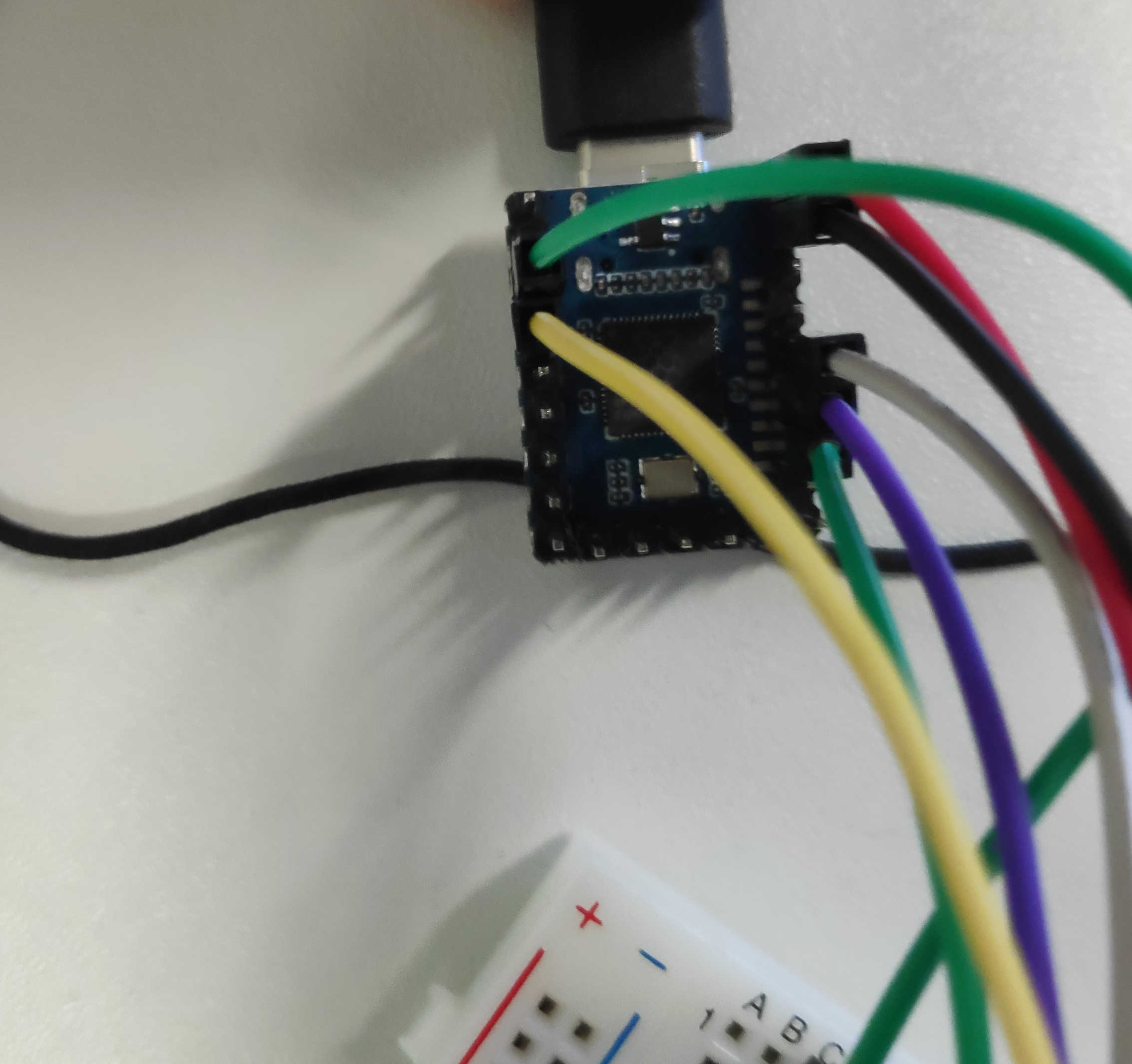
For the real-life example I used first “waveshare RP2040-Zero”, which has multiple I2C Pins. These need to be enabled manually via the Wire API by setting the pin for SDA and SCL. In this configuration the Servo signal is connected to pin 5, Button pin to 2, potentiometer to A3 and the I2C connection from the LCD to pin 9 (SCL) and pin 8 (SDA). I also change the Button from pull-down to pull-up, so the code needed to be adjusted later on. Depending on the board the pin for the SCL and SDA needs to be set manually via wires lib. The code needed to change as following:
                #include <Wire.h>// depending on the board this Line can be disabled

                int SERVO_pin = 5;
                int BUTTON_pin = 2;
                int POTENTIOMETER_pin = A3;
                int LCD_I2C_adress = 0x27;// 20, 27 , 3f


                void setup()
                {
                    // Add in addition these lines
                    // depending on the board these Lines can be disabled
                    Wire.setSCL(9); // Setup Pin for Comunication
                    Wire.setSDA(8); // Setup Pin for Comunication
                  ...
                }

                void loop(){
                    ...
                    // Instead of bool BUTTON_status = (HIGH == digitalRead(BUTTON_pin));
                    // USE this:
                    bool BUTTON_status = (LOW == digitalRead(BUTTON_pin));
                    ...
                }
                ...
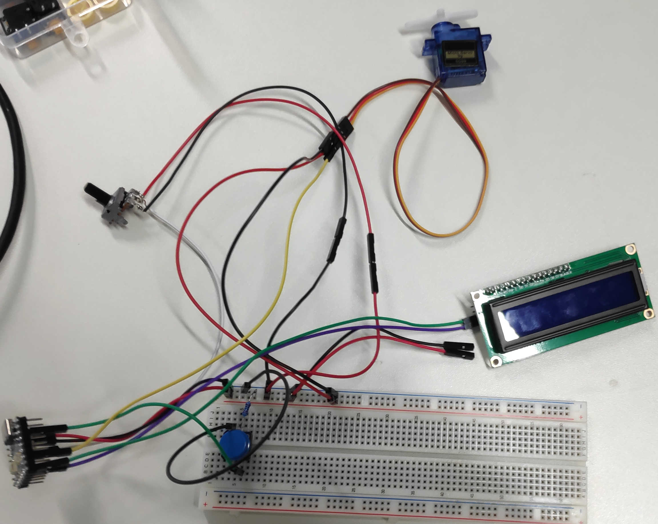
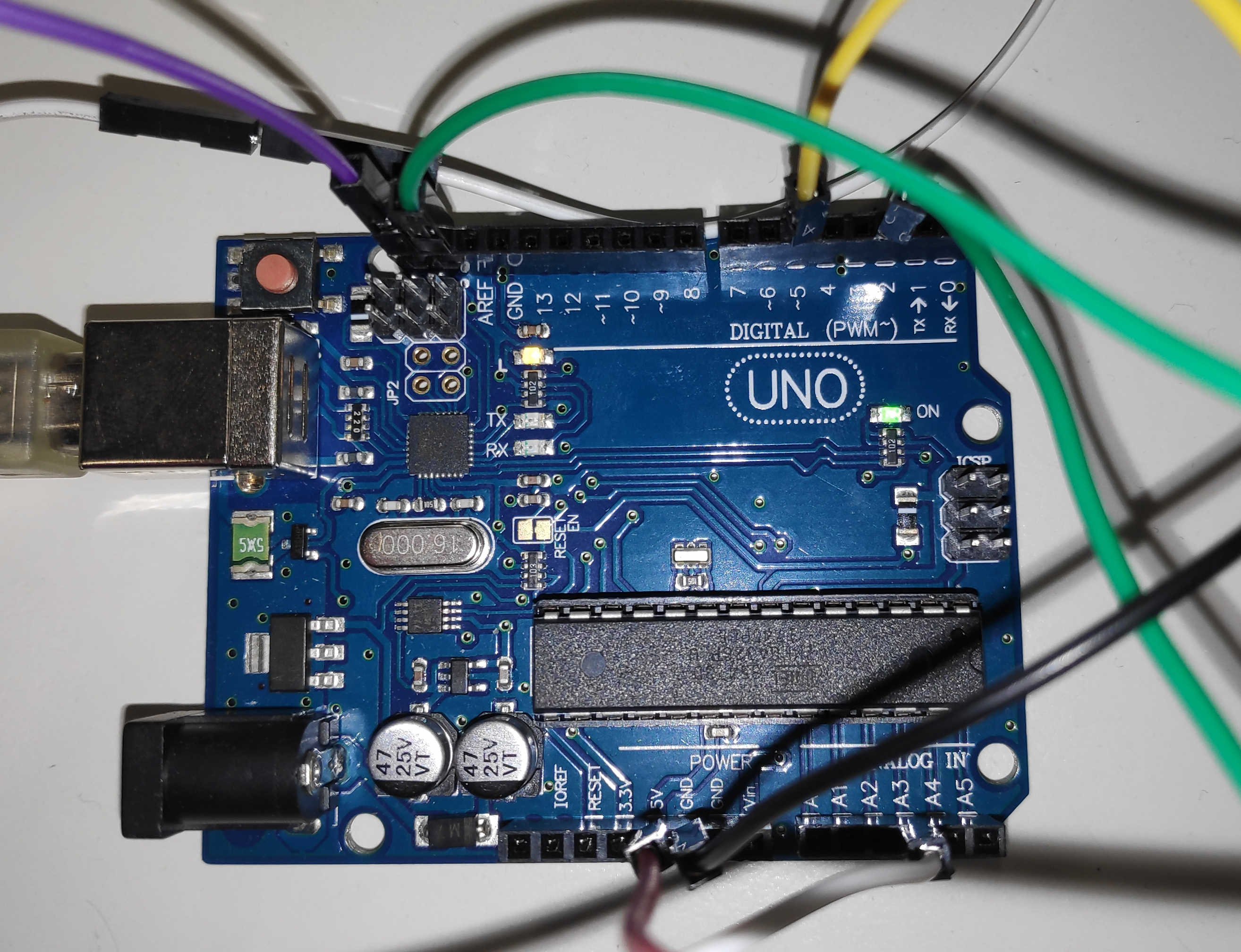
After trying out this combination, it turns out that the servo-motor doesn't get enough power from this board. I switch to a normal Arduino Uno, but keeping all the pins as described for the Pi Zero. Below is the video and wiring. The result looked like this:
Here are the following files used: