Week 6 – Embedded Programming
The task for this week was to write an embedded program. This program should than work on a self-designed circuit. The circuit should contain 3 LEDs and 2 Buttons controlled by an Arduino Board. Each LED should be turned on or off by using only 2 Buttons for all LEDs.
First step for this task is to create a circuit, which can be than used as a base for the code. To read or write any signal from the Arduino, it’s is important what type each port is and where it is located. Looking at the “Arduino uno”, it has digital In/Out -puts from port 0 to 13. Further more the Arduino has a 5V Power Port and a GND, which can be connected to. For this task it’s only Important to focus on the 5V power, and the Digital in- and outputs.
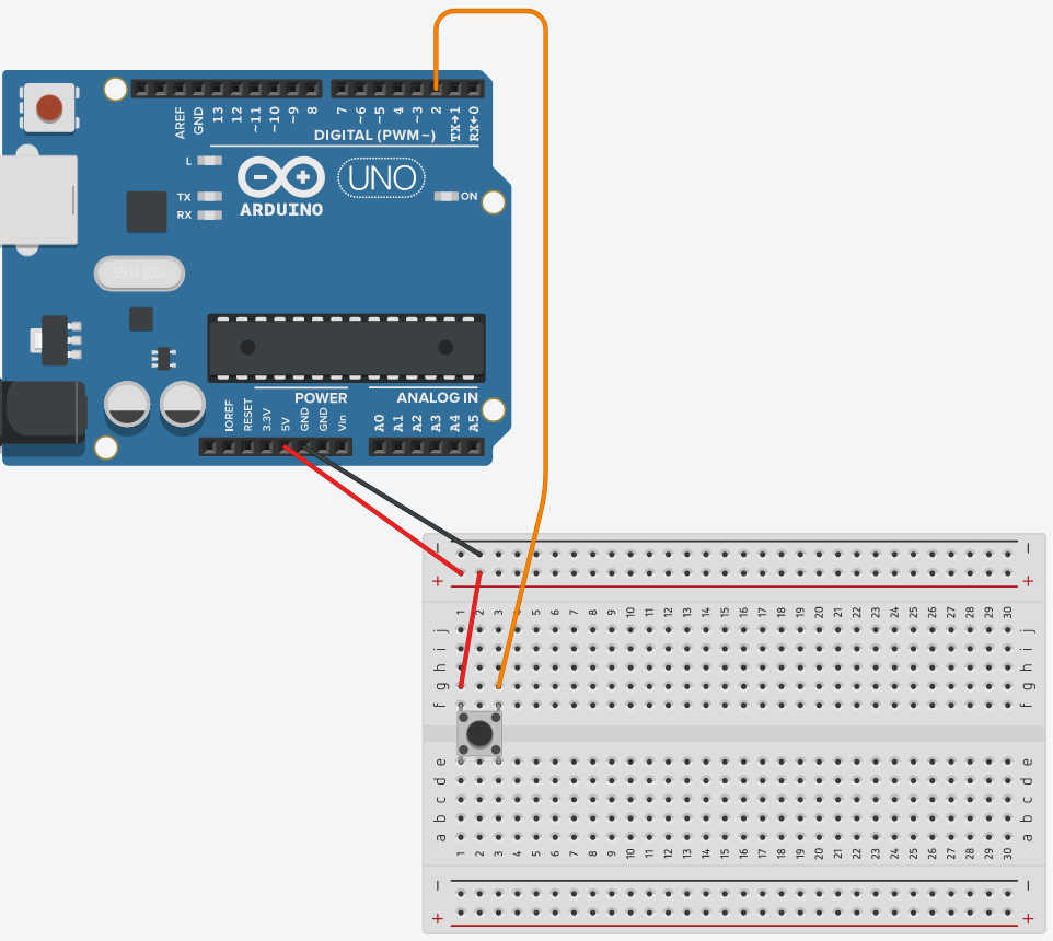
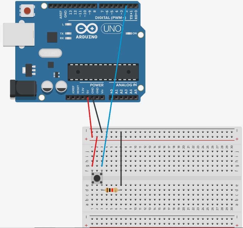
Beginning with the connection of the buttons, each of them needs a digtial port to read it’s button status. This digital port detects only weather the voltage is High or Low, which is determent on based on a Voltage threshold. Connecting the button with a power source creates an electricity flow, when the button is pressed down, setting the digital read Signal to high. Is the button not pressed the digital signal than should be than low. The button needs also be connected to the ground (GND), due to a phenomenon called floating. This creates a short circuit, because the voltage at GND doesn’t get nullified. To prevent it, a resistor is need to reduce the electric current to near 0A. For 5V and this particular board a Resistor with about 10 kΩ reduces it to 0.05 mA, which is good enough for this circuit.
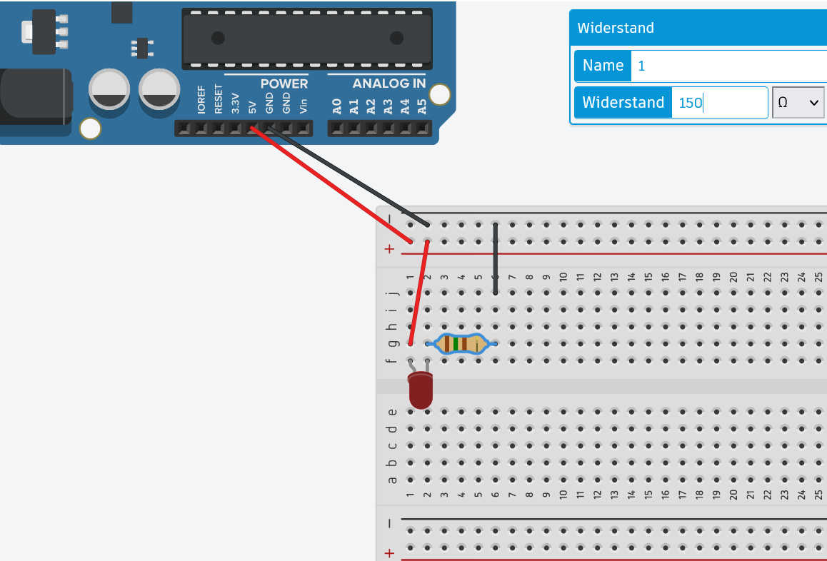
To connect the LED to the circuited, it needs a power source and a GND to close the circuit. An LED can only bear a certain amount of electrical current running through it, thus a resistance is needed to reduce the load on the LED. The need Resistor can be calculated by getting the resistance difference between RLED and R circuit . R LED can be calculated with the I max current of the LED of 20mA and V LED Type voltage of the LED 2V, creating a resistance of about 100 Ω . Depending on the LED the Voltage and max Current can change. In my example I used red LED , which had all the same resistance. R circuit or the resistance needed to reduce the current in the circuit, can be calculate from I max 20mA, because the current stays consistent in the System, and the voltage V power of 5V, resulting in 250 Ω . The required Resistor is than the difference from 250 Ω – 100Ω, which is 150Ω. Connecting this Resistor between LED and GND.
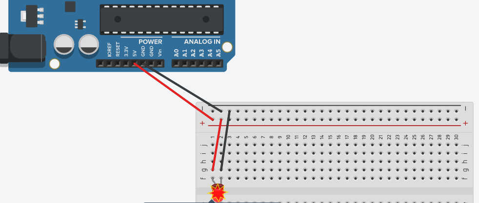

Second thing to be keeping in mind is the side of Anode and Cathode, because the current can only flow in one direction through the LED. The flat Side of the LED indicateds the Cathode and needs to be connected to the GND and the Anode needs to be connected to the source. Since I need to control the on or off status of the LED, the power source needs to be controlled. To Archive it, I replaced power source with the digital output. When I set this digital Port High, the LED will turn on and if I set it to low the LED will turn off.
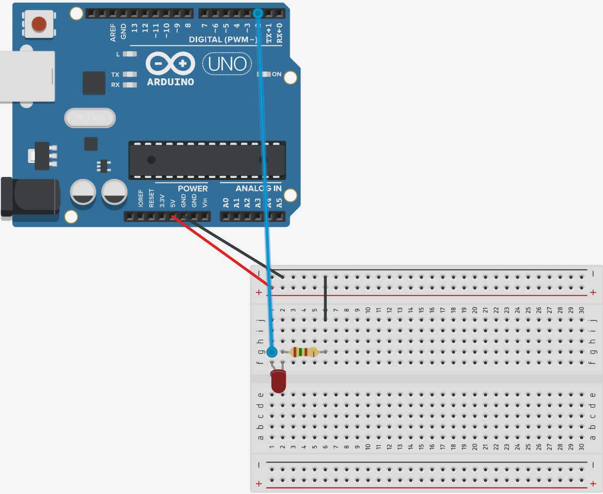
Putting it all together the circuit looks like this:
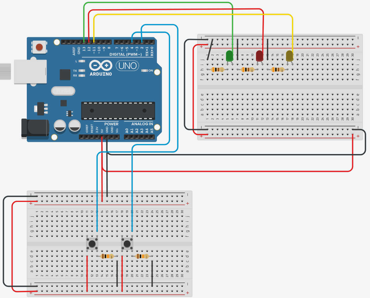
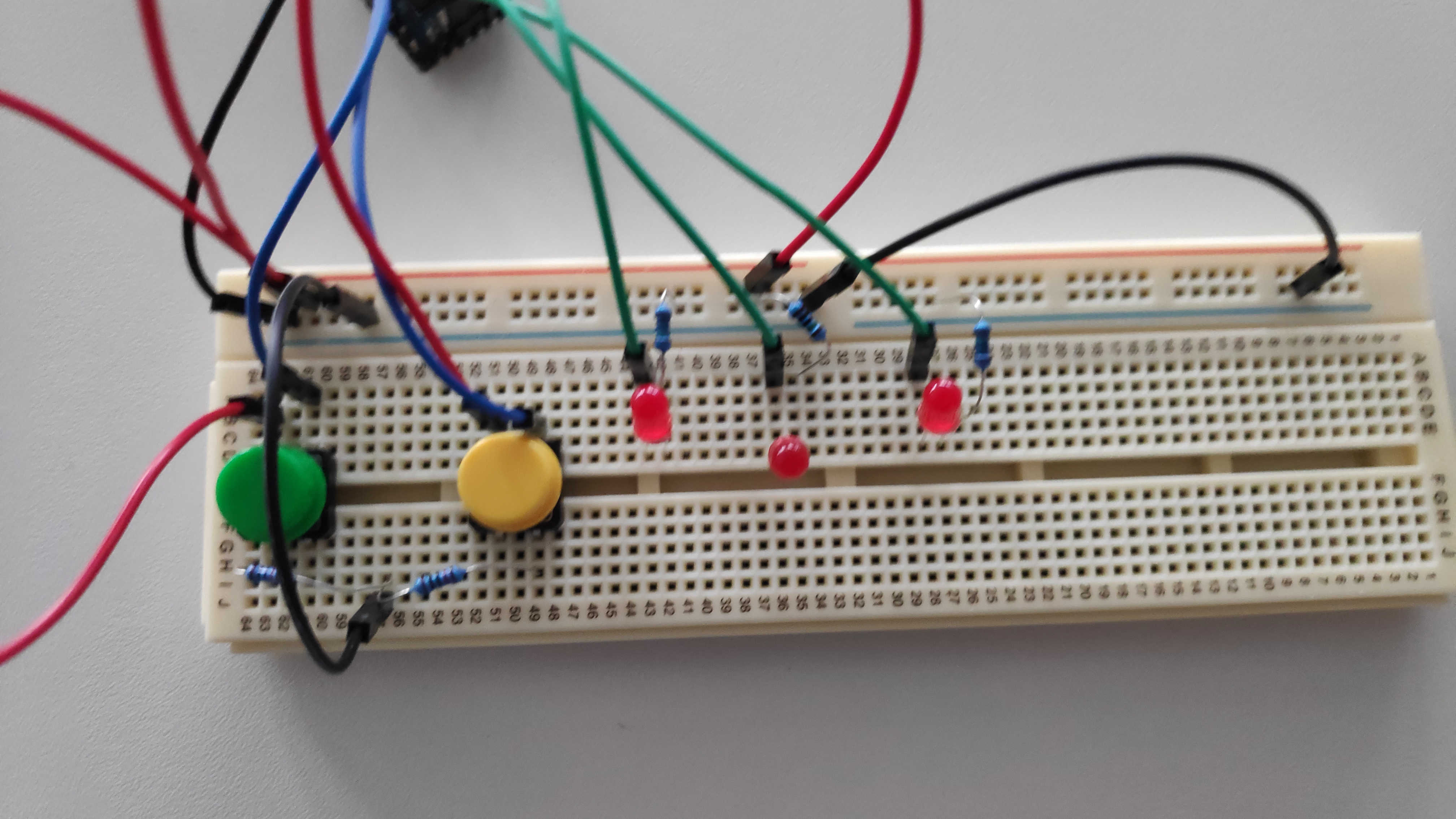
After Designing the circuited as descried above, I could connected a real micro controller with a circuit. For this I used the described design, but using an “Raspberry Pi Zero” as the controller. I placed the components on a breadboard connecting the lanes on the board with M-M Cable. Connection to the Micro controller I used M-F Cable, because it used a Male adapter on the board. The GPIOs Pin 2 and 5 were used by me as Digital Input for the buttons. The Pins 11, 12 and 13 I used as Digital Output Pins for the LEDs. Lastly I connected the GND and 5V Power from the controller to the Breadboard. I used a small breadboard, so I needed Jumper cables to connect both board-halfs GND together. Else you might be wondering why the LEDs won’t light up or the buttons don’t work.
To create the Code for this Board, the idea was it to use one Button to turn a LED on or off and the second Button to switch between each LED. To make the LEDs scalabil and easy to iterate through I used an Array to save each Pin Number and with another Array I saved the status of the LED if it turned on. I set up the LEDs by going through the Array and setting the configuration for each port as digital output starting the LED in off Mode. Setting up the Buttons I simply saved the pin number and set the pin mode to Input.
            // C++ code
            //
            const int BUTTON_pin = 2;
            const int BUTTON2_pin= 5;
            bool BUTTON_status = false;
            bool BUTTON2_status = false;
            bool BUTTON_temp_Status = BUTTON_status; //temp Variable that caches Button Status

            const int LEDs_Pin_length = 3;
            int LEDs_Pin[] = {13,12,11};
            bool LED_Status[] = {false,false,false};
            int currentIndex = 0;

            void setup()
            {
                //SERIAL PRINT
                Serial.begin(9600); // open the serial port at 9600 bps:

                pinMode(BUTTON_pin, INPUT); // Input as Button
                pinMode(BUTTON2_pin, INPUT); // Input as Button

                // Button Setup
                for(int i = 0; i < LEDs_Pin_length; i++){
                pinMode(LEDs_Pin[i], OUTPUT);
                }
            }
The Main Loop is configured to read the current button status and saving it. If Button2 (Pin 5) gets pressed it increases a index number to 1 and using a modul operation, let it only increases to the maximum size of the led. When the maximum is reached it will be rest to 0 starting all over again.
            void loop()
            {
            BUTTON2_status = (digitalRead(BUTTON2_pin)== HIGH);

            if(BUTTON2_status){
                currentIndex++;
                currentIndex %= LEDs_Pin_length;
                delay(100);
                Serial.println("Butten is Selected "+String(currentIndex));
            }
            ...
            }
The Button 1 (Pin2) has the purpose to turn the select LED on or off. The selected LED is determent by the Index variable described above. I only wanted that the LED turn on or off once, if I hold the button, thus I used a bool to store the status of this button on loop before and compare it with the current status. When the current status has changed to before and it is set to high, meaning it was pressed, I execute a function to turn the led on or off.
            void loop()
            {
            BUTTON_status = (digitalRead(BUTTON_pin)== HIGH);
            ...
            // When Button is hold down, it shouldnt switch between on and off
            if(BUTTON_status && BUTTON_temp_Status != BUTTON_status ){
                Serial.println("Butten is Pressed ");
                setLED(currentIndex);
                delay(100);
            }
            BUTTON_temp_Status = BUTTON_status;

            }
The setLed Function takes in the current index of the LED and uses this to check in the saved Status of the LED if its on or off. Mapping the opposite of the Current Status of the LED to the Status Low and High, the desirable status can be readout. DigitalWrite can be than given this status and the pin of the current selected LED Pin to write it status. Than change the current Status from this led to the opposite status. The result of the program should look like this:
            void setLED(const int& index){
                // False == LOW; true == HIGH :
                int status= map(!(LED_Status[index]), false, true, LOW,HIGH);
                digitalWrite(LEDs_Pin[index], status);
                LED_Status[index] = !LED_Status[index];
            }
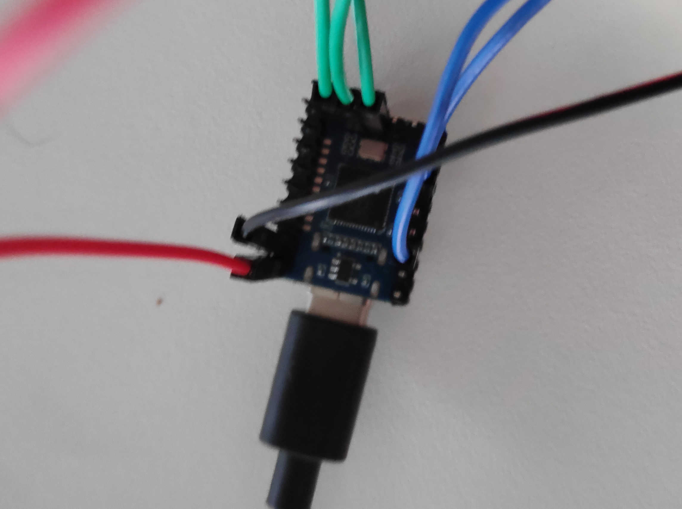
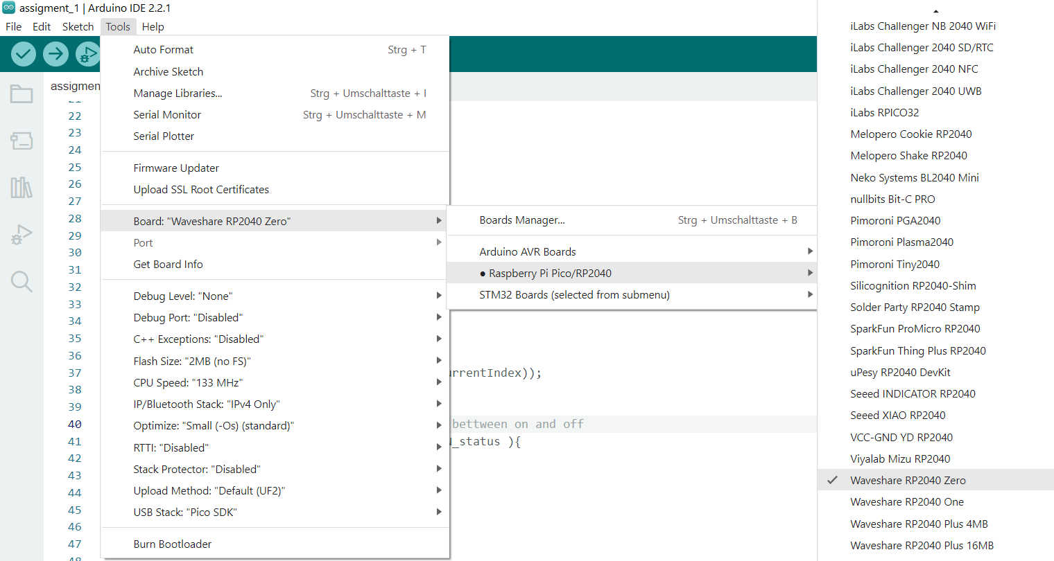
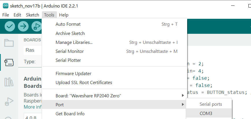
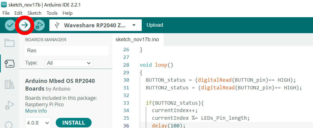
Uploading this program to the “Raspberry Pi Zero” first only connect the micro-controller without the circuited to the pc. If it’s start blink, this indicates that the micro-controller itself works. Opening the Arudino IDE, it is possible to connect to the board. Go under tools > boards and select the wanted board. If it the wanted board series doesn't show up you have to manually install this board. For this depending on the board follow the a install tutorial or select board Manager and install the wanted board. To install the “Raspberry Pi Zero” I followed this tutorial:https://www.waveshare.com/wiki/RP2040-Zero. Now you have to open the USB port for the controller by going under Tools > Port . Select the Wanted port, where the Raspberry Pi is connected. Now just press upload on the IDE to upload and compile the code. The program should be now uploaded to the controller and be directly executed.
Using the real Board it creates the result like this:
Here are the following files used: