Week 5 – CNC milling
This week assignment was to create a CNC cut shape, which was cut from a Styrofoam cube. This includes some shapes easily made with a CNC-mill. For a 3-Axis CNC mill task like Engraving, Cutting Planar Face or Simple 3d shapes can be cut produced faster with a CNC mill than with a 3d-Printer. However, this removal Technique has some drawbacks, for example a CNC mill cannot cut overhanging arches in certain directions without reorienting the Structure. Or Objects inside another Object is plain impossible to create. Furthermore you have to watch out, that collisions with the milling-bit doesn’t happen. To design this week’s model I had to keep this in mind.
To show how smooth a CNC-mill can machines a surface, I decided to make a round/ curved model. I also wanted to include some ”hard edges” to show the versatility of the CNC. Using “Fusion 360” I created a 3d model and generated the G-Code for the CNC mill.
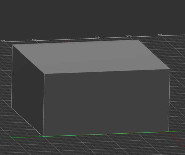
Firstly a created a Box, which represented the volume of the material, that I wanted to cut. This box can than be used, to check if the created 3d Model fits inside it.
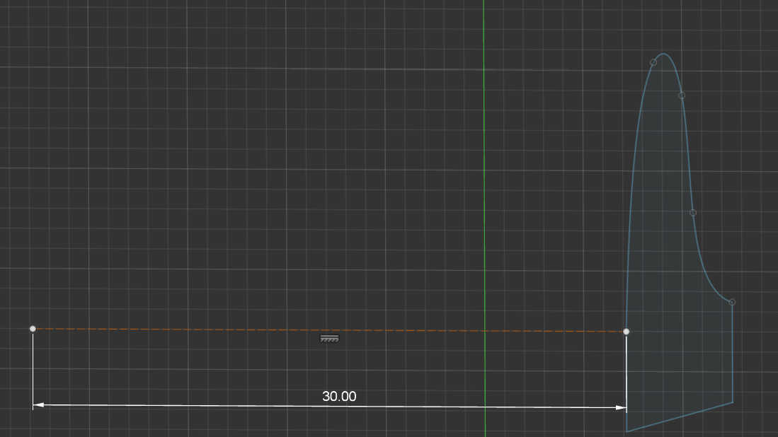
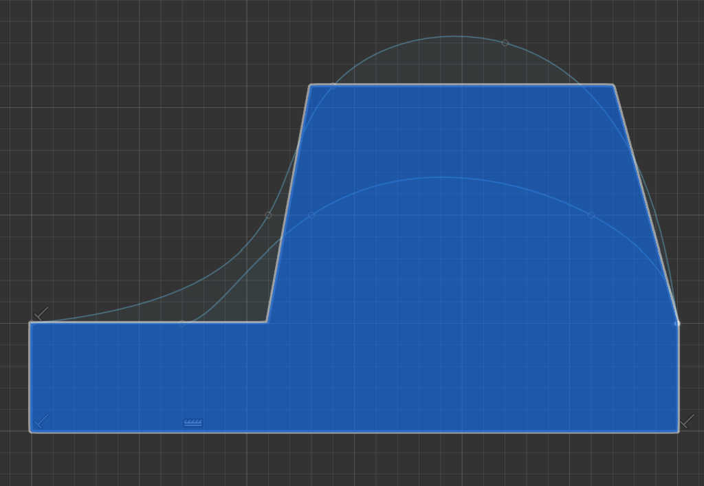
In the next step I began creating the main Model by defining a profiles with sketches. This first profile works as one end of the model. I used curves to make the surface round and added some “hard edges” with the line tool.

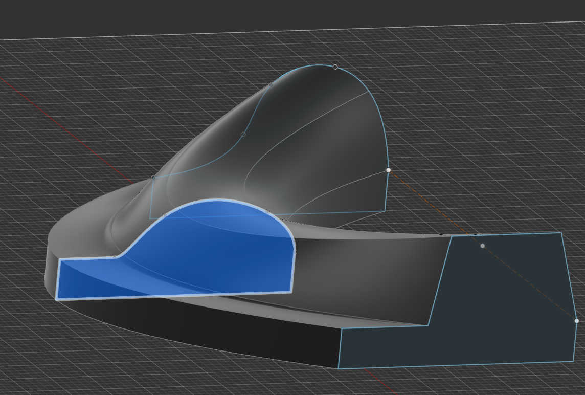
To make it 3d I could have extrude this shape, but I decided to have a transition between 2 profiles. I created a construction line to place a new sketch at a distance from the first shape and than place this second sketch at this distance. The second Profile works as a transition shape between both endpoints of the model. I made this shape a bit smaller from the original shape, which would later create a slope.
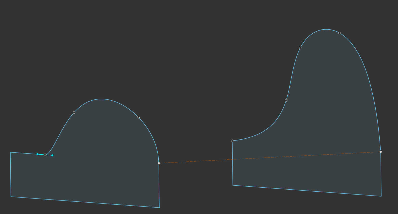

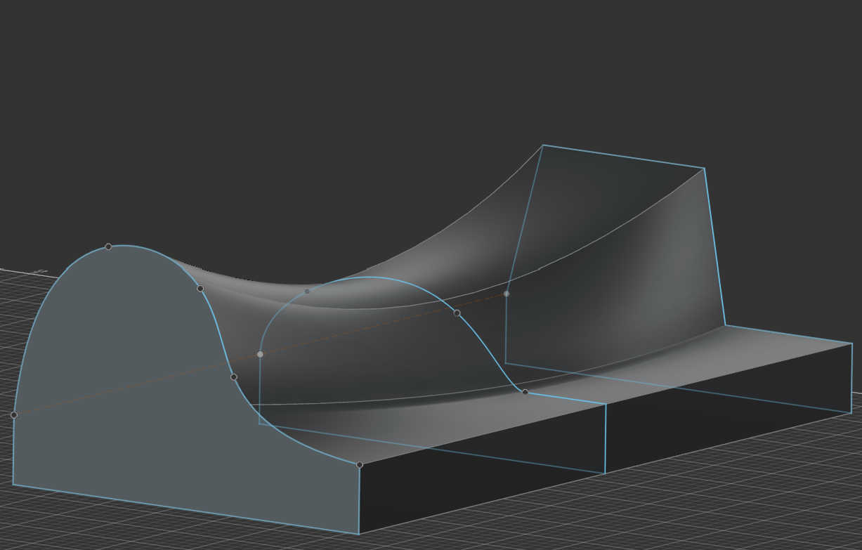
The 3rd and end profile consistent of a hard edged shape, which created a smooth to hard edge transition. For this I created a sketch, which is the same distance away from the last sketch, with only using the line tool to created some “hard edges”.
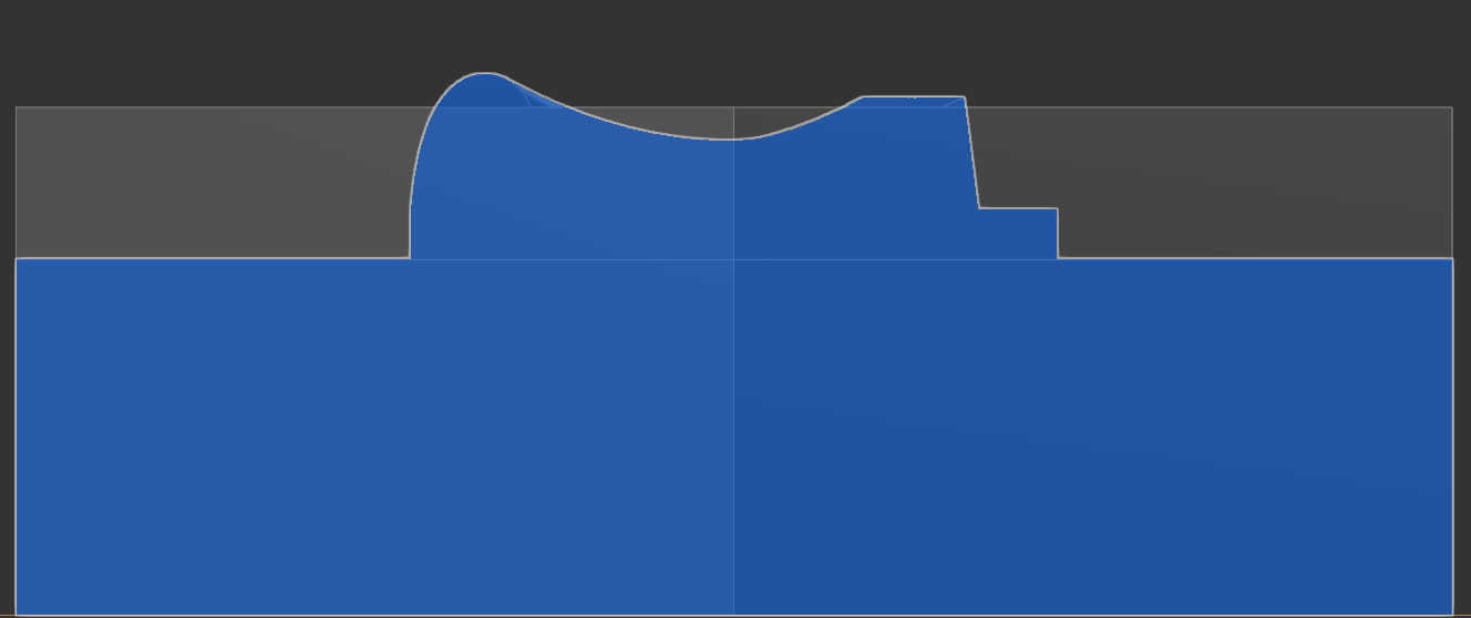
To make these sketches 3d I used the loft modifier and selected all sketches. This creates a 3d model based on the profile and adding a transitions between each profile. For this to work each Profile needs to be aligned to create a straight line, else the model will be scoured.
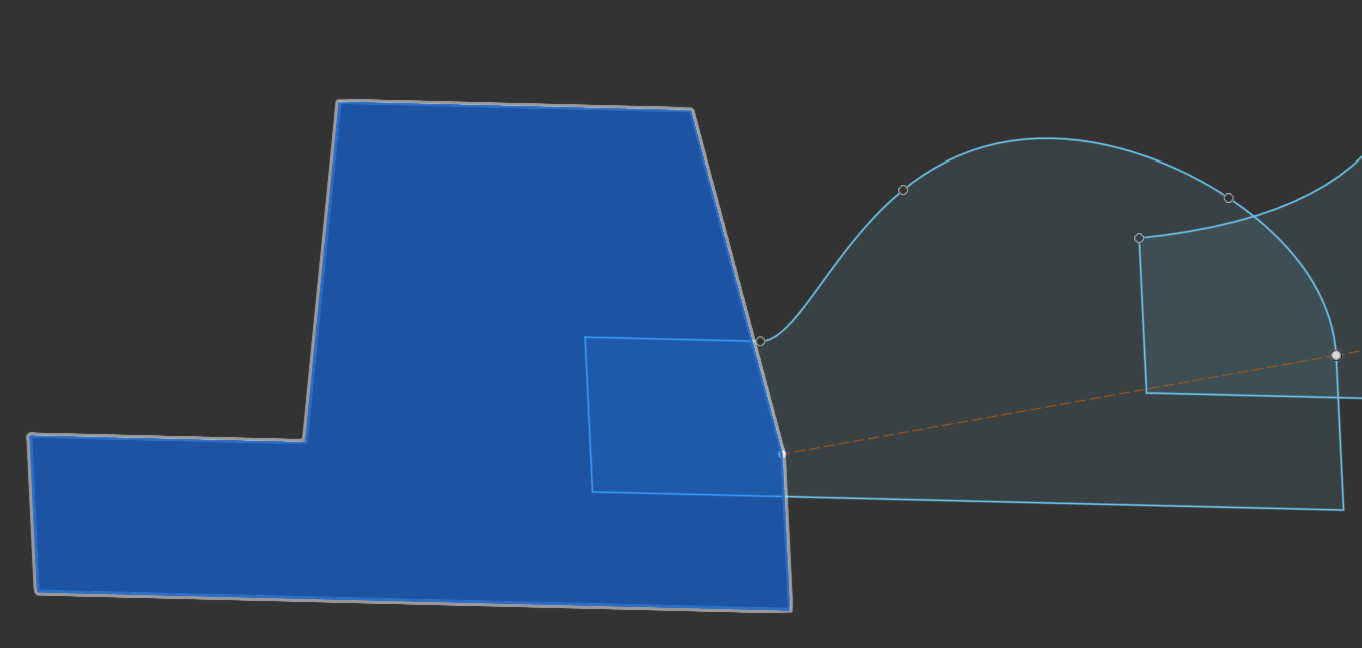
The new created Shape can than be used to check, if it fits into the material by comparing its size to the cube. If it doesn’t fit the model needs to be scaled down. To let the CNC know how deep it needs to mill inside the material, the placeholder box can be used to place the model on the wanted position. Don’t forget to lower the height of this Box, so the whole model still fits inside the material.
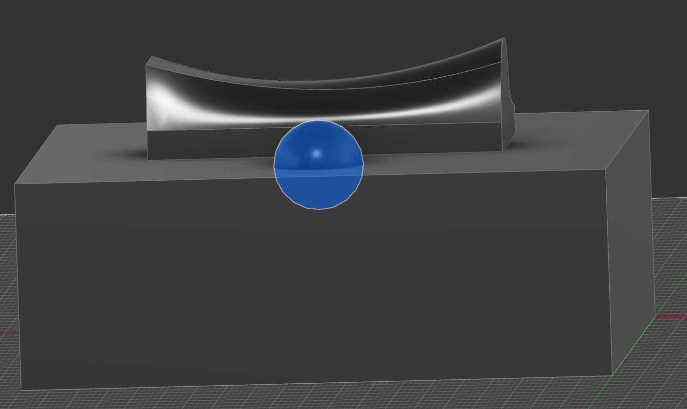
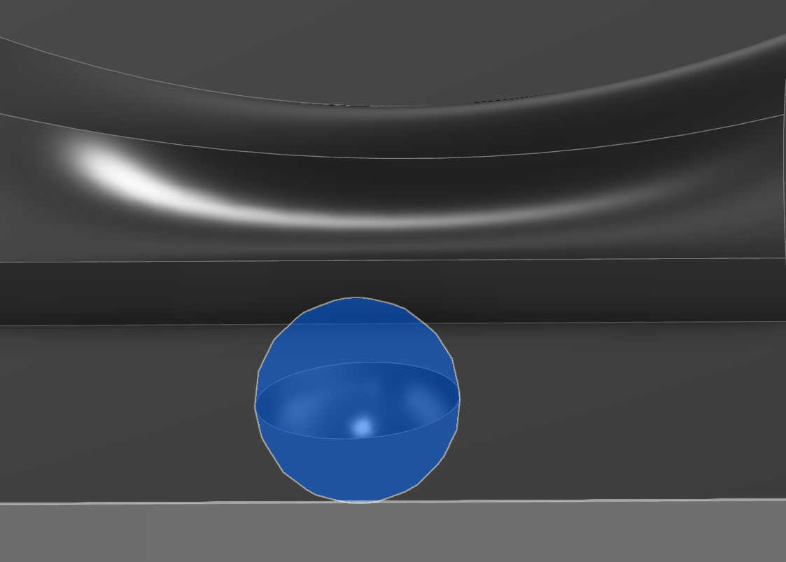
When done right, this new box can be than be edited to cut more shapes from the material. I used a sphere to cut inside the box to create a half-Sphere cutout on the material. This technique works as a kind of alternative Method to create a shape out of the material, by simply removing Forms from the Material directly.
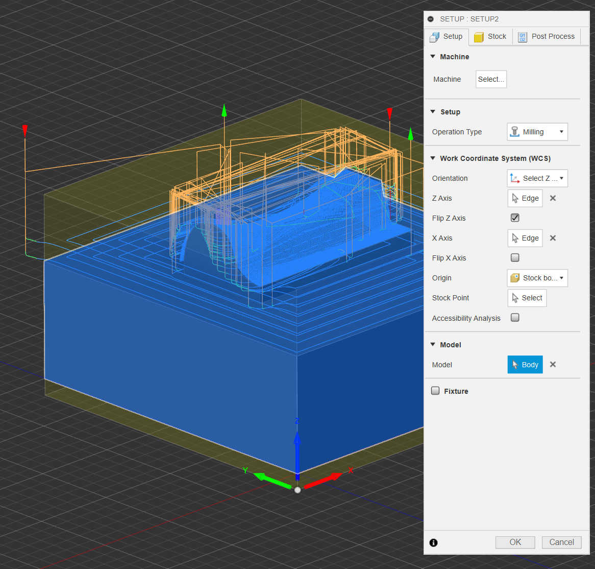
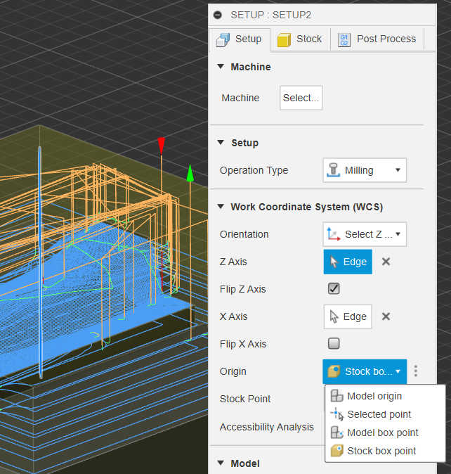
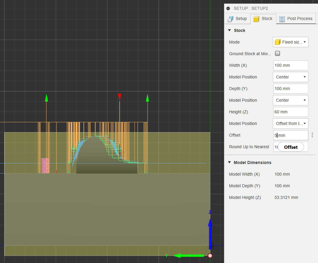
Lastly to make a later conversion easier I combined the modified box with the created object to create one body. This body than can be edited in “Fusion 360” Manufacture mode. Create a new Setup using this model allows it to be setup for milling. First set the direction of the origin of the bottom corner of the model. Depending on the CNC its the left side corner on the x axis. If the Model is a bit Shorter than the actual box, offset the bounding box downwards in the stock menu to reduce the material removal from the CNC. I used a presets file for the tool-bits and mostly preset settings for the setup. To use this preset, deactivate the history of the file and copy and paste the wanted model in this file. If the orientation isn’t right, use the rotation tool to correct it. Than edit the setup by clicking right-click > edit and select the new model. Because my model was a shorter I offset the bounding box.
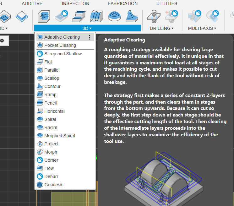
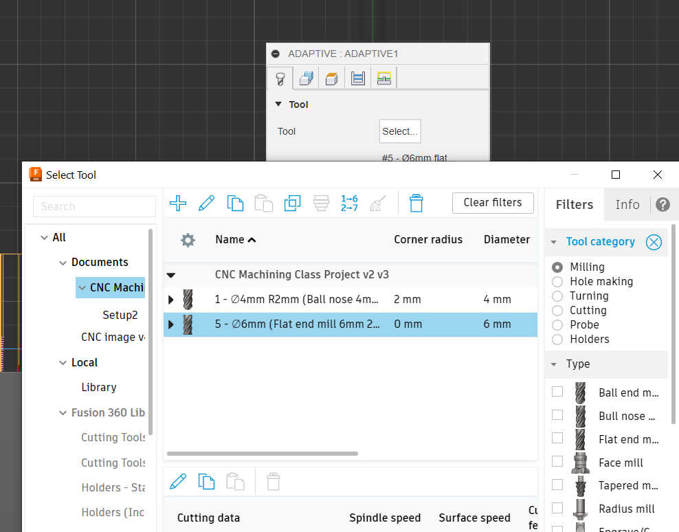
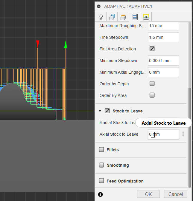
Next Step is to select the method I want to use for milling. For most first step in 3d Milling you want to remove most of the material, so I selected the adaptive method with a flat end tool-Bit for the first step. Don’t forget to set the stock to leave in the Axial direction to 0mm, because this method works as the final finish for the flat surfaces. All jobs afterwards are only used for round surfaces.
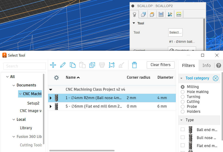
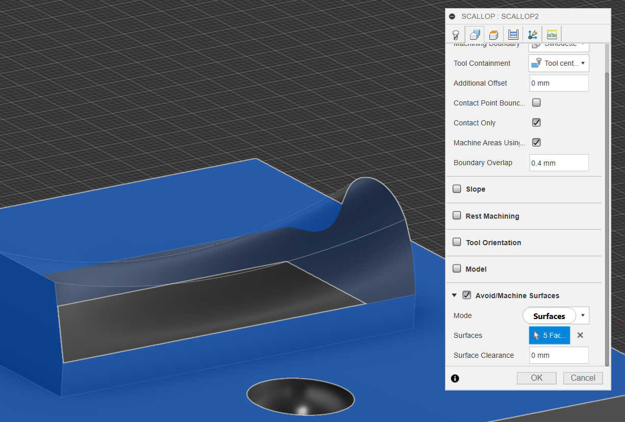
The Adaptive method creates only a rough cut, thus a second method or more are needed to smooth the surface. As a second job I used the method scallop with a ball end tool-bit to round the surface. To make sure flat surfaces are not getting rounded with the ball end, I selected all flat surfaces in the “Avoid/ Machine Surfaces” option under geometry. This restricts the tool bit to only milling faces that are not flat.
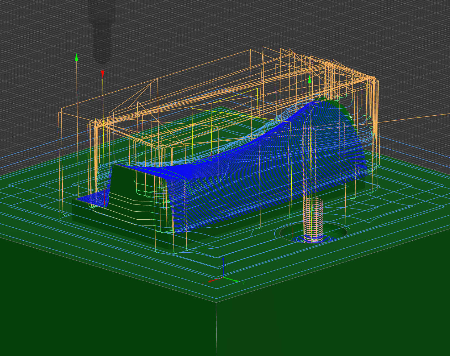
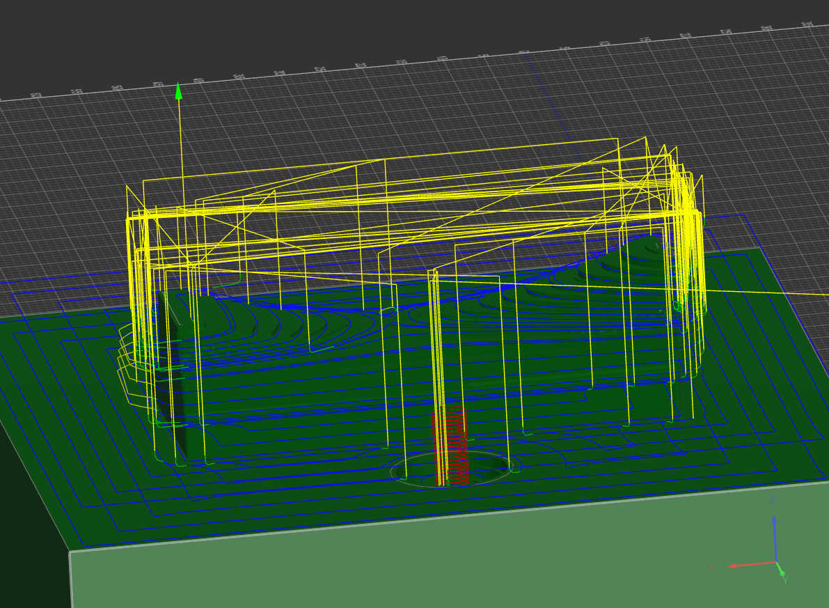
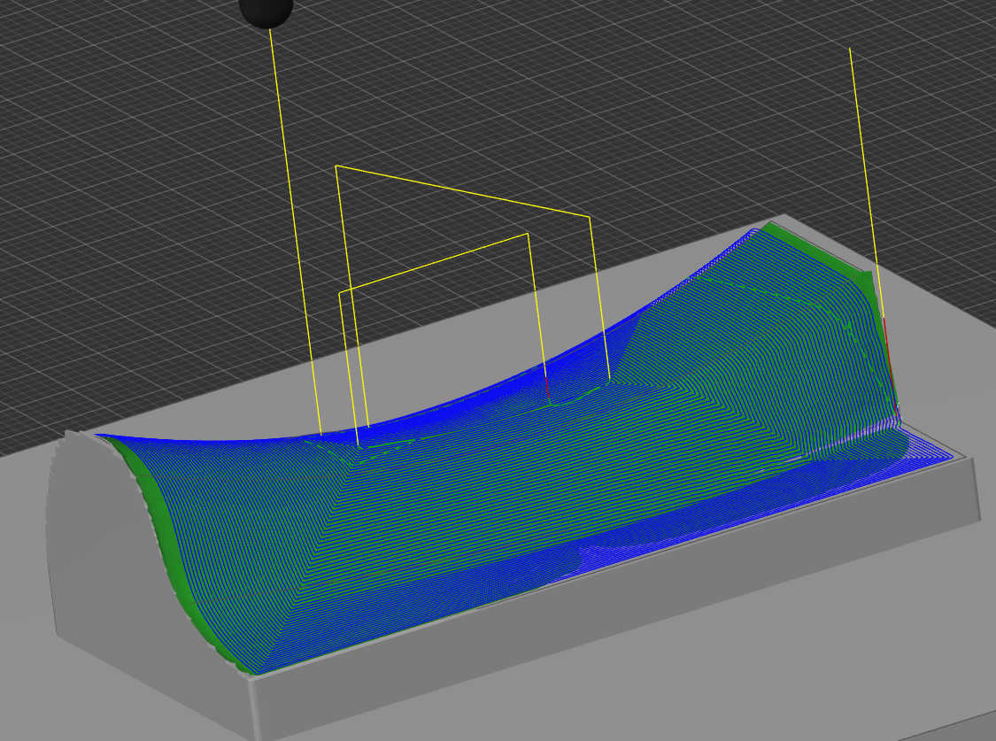
After all Method are selected its important to check in the simulator, that the faces get removed as wanted. This tool can be also used to check if any collision with the tool bit occurs and a time estimation of the job. This was case for me, because I forgot to select the flat walls of the model. After fixing this the job , everything was ready to be exported.
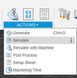
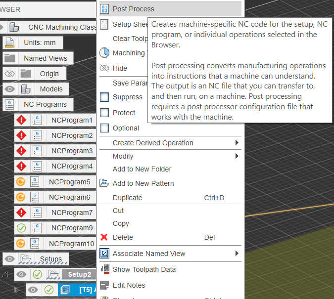
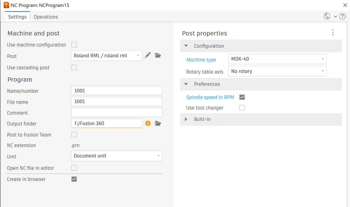
To run a job, each job needs to be manually exported as a file. Simply right-click on the job and select post processor. This will allow you to name the job you want to export, set the machine you want to use and the file directory. After saving the file, transfer it to the device, that is connected with the CNC machine.
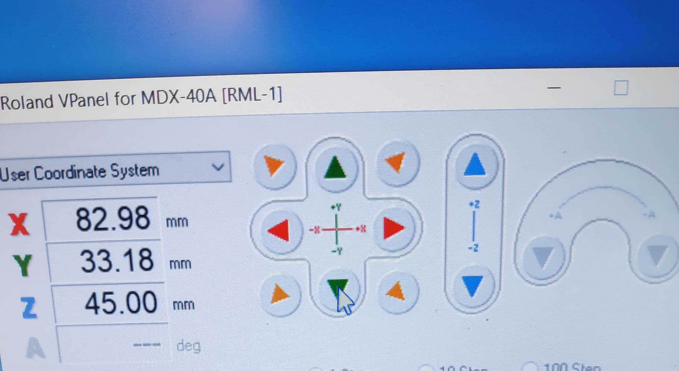
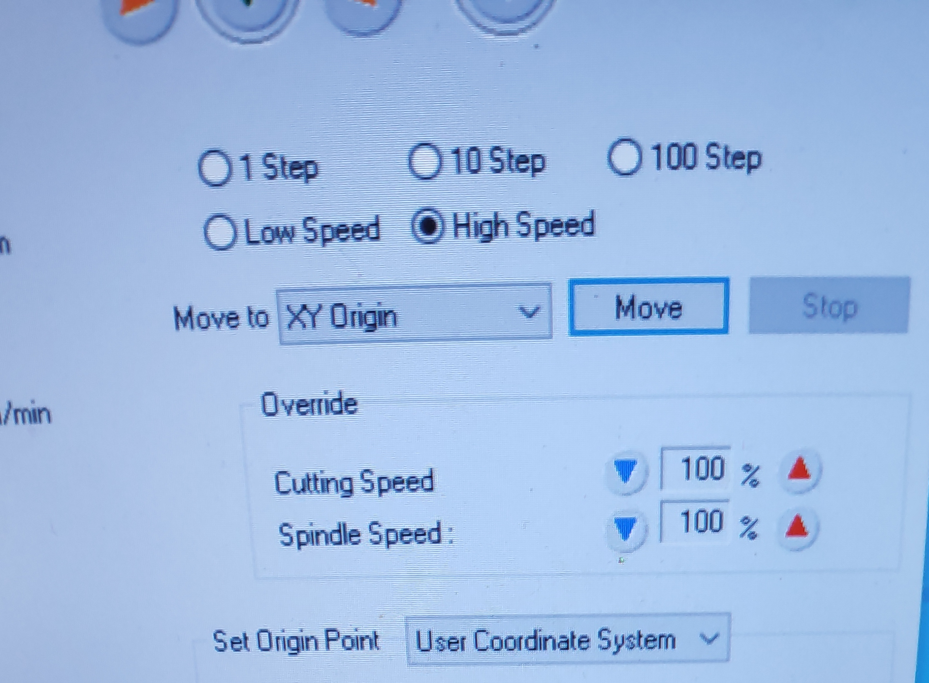
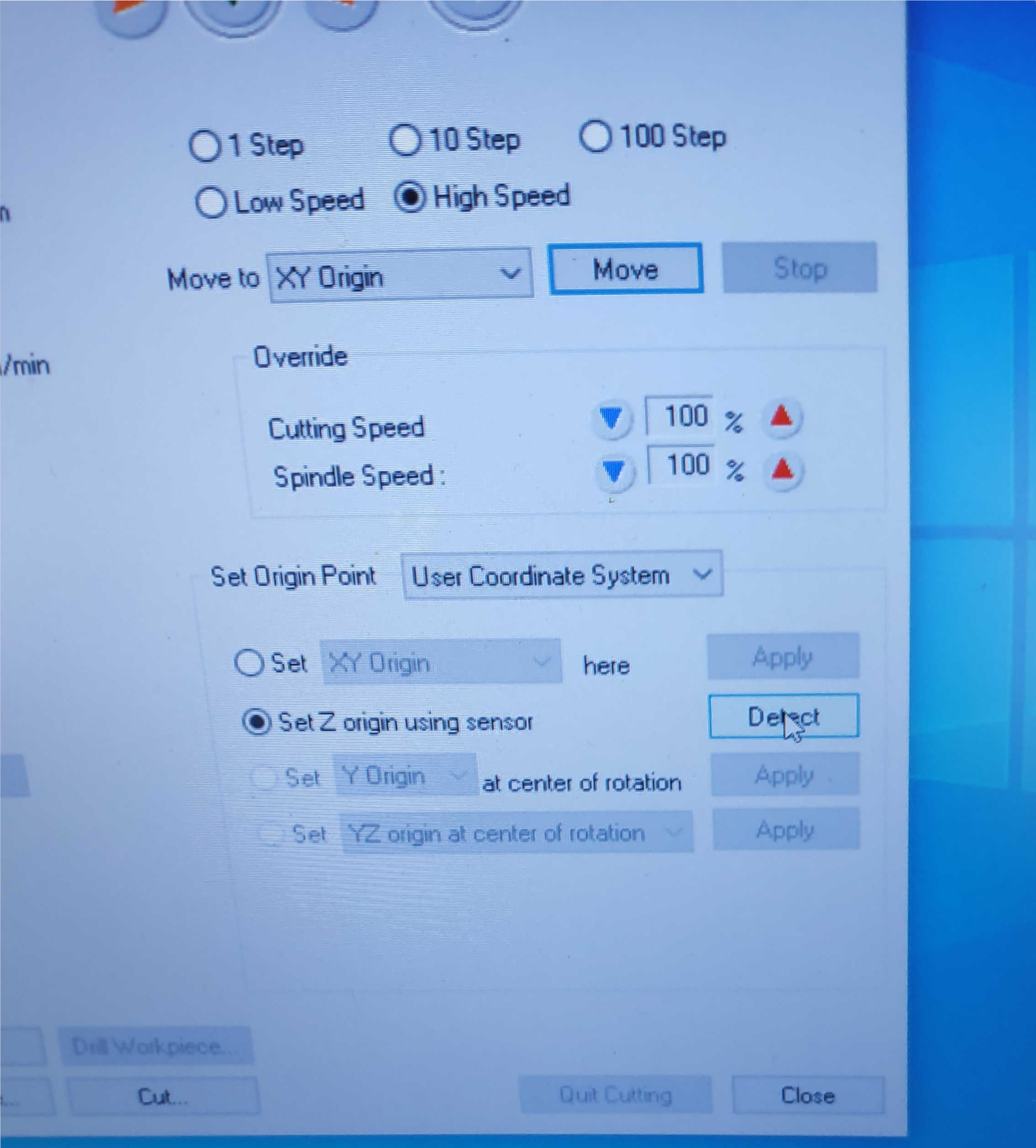
Setting up the CNC mill you first need to stick the material on the milling platform. I used a double-sided tape to glue it in place. Next step is to put in the wanted milling bit for the job. For the first job it would be the flat-head bit. Than you have to calibrate the machine on its xy and z -axes for this bit and model position. The xy axes can be calibrate manually by moving the bit over a specific corner in such a manner, that the midpoint of the bit is aligned with this corner. For this CNC machine it was the left corner that needed to be aligned with the flat-head bit. Select in the program set XY Origin and press apply. If done right, the user coordination should now be 0 in x and y direction. You can check if the machine rightly applied the x and y coordination by pressing move in the option, which will move the head of the mill to the calibrated point.
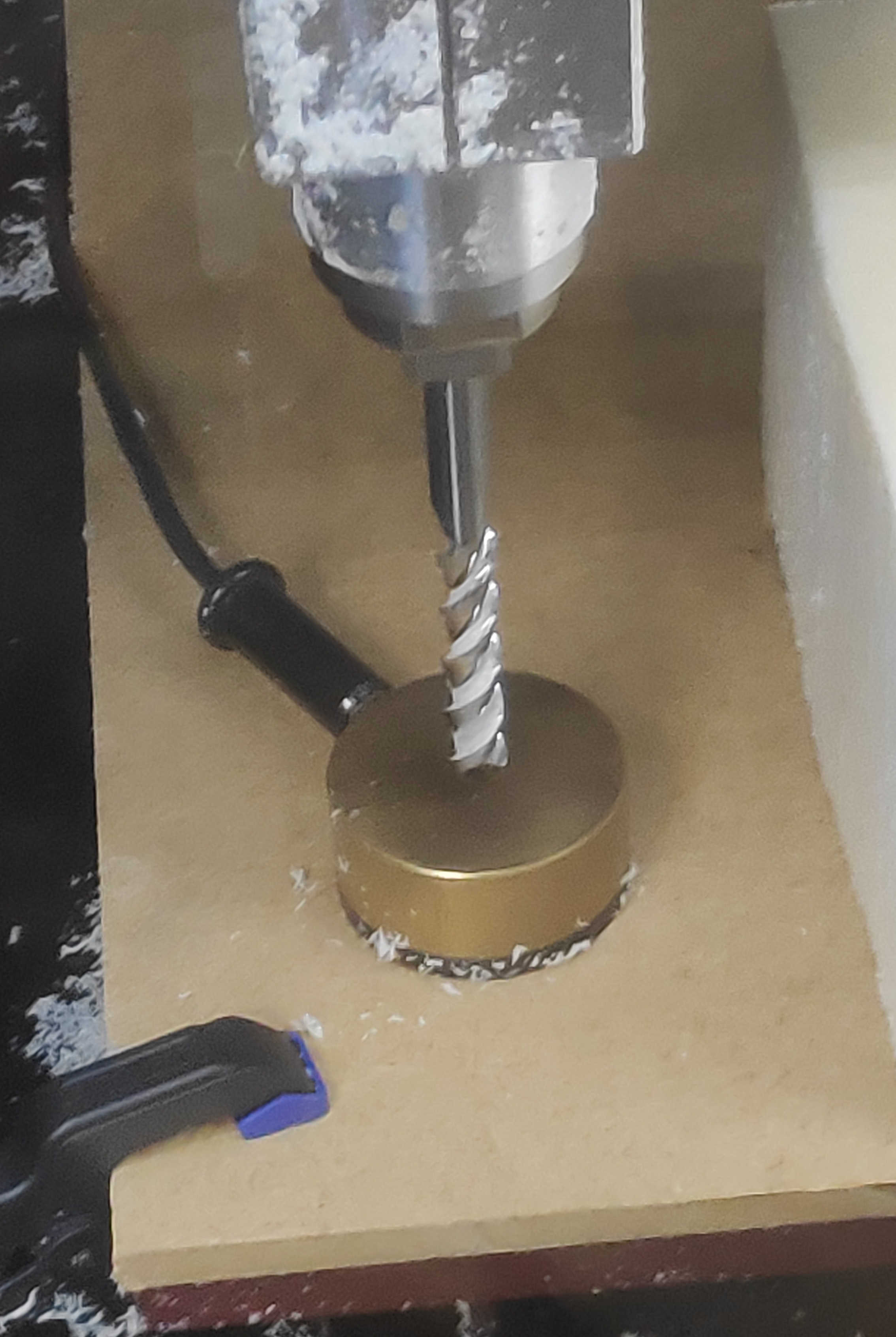
Afterwards the z-axis can be calibrated semi- automatically with a puck. For this move the bit outside the material to a free space and lower it with enough space below, that the puck can be still fit under. Place the puck under the milling-bit and select detected on the CNC software. The machine will than lower the puck downwards until it touches the puck and will automatically go upwards again.
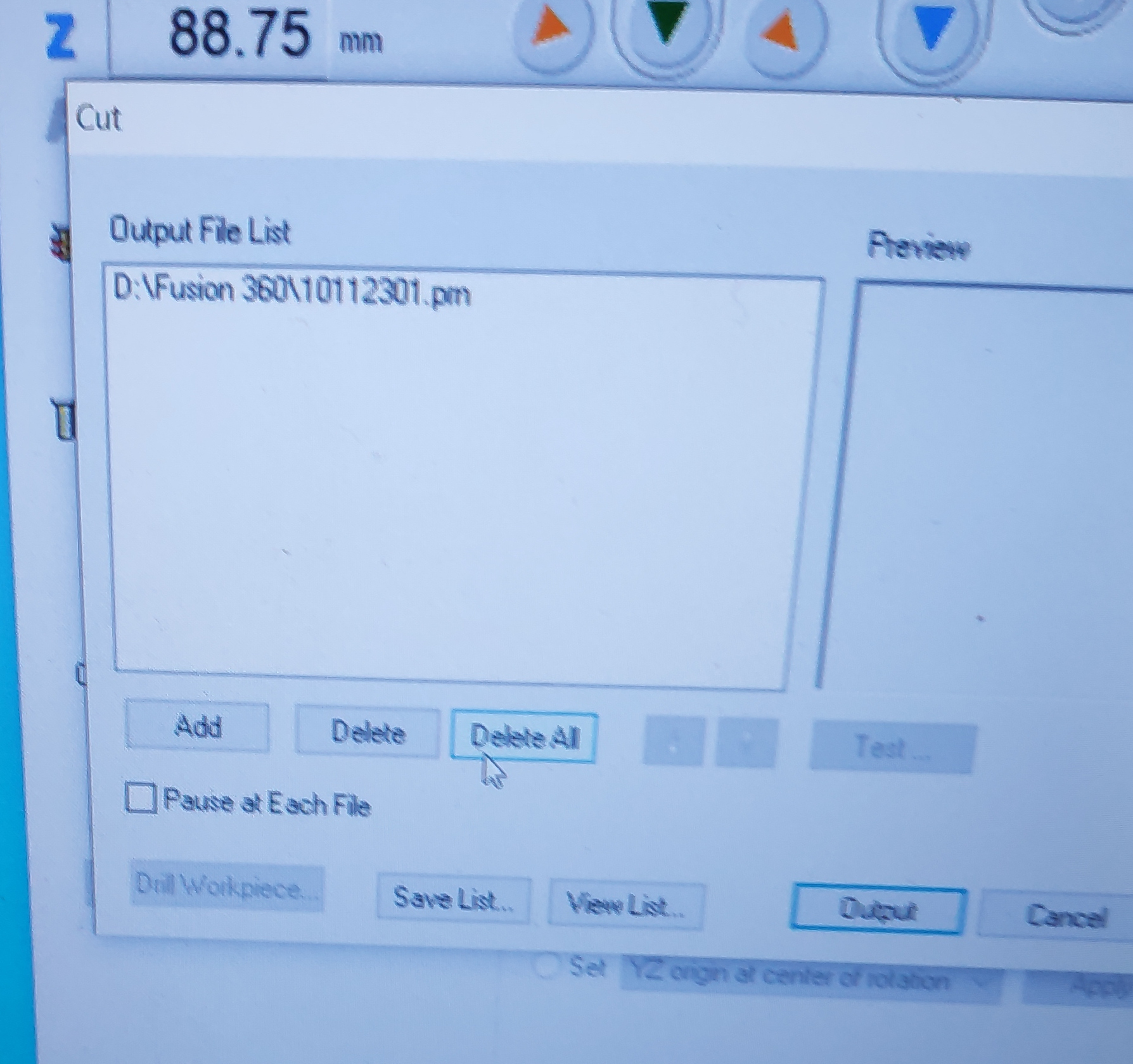
Now the setup the file can be loaded by selecting cut. If previous jobs are occurring, remove them from the list. I firstly only loaded the first job in the milling program and hit output, because each job list needs to be executed based on the same milling bit. By hitting output the milling process will start directly, therefore be directly able to stop the CNC mill when pressing the button.
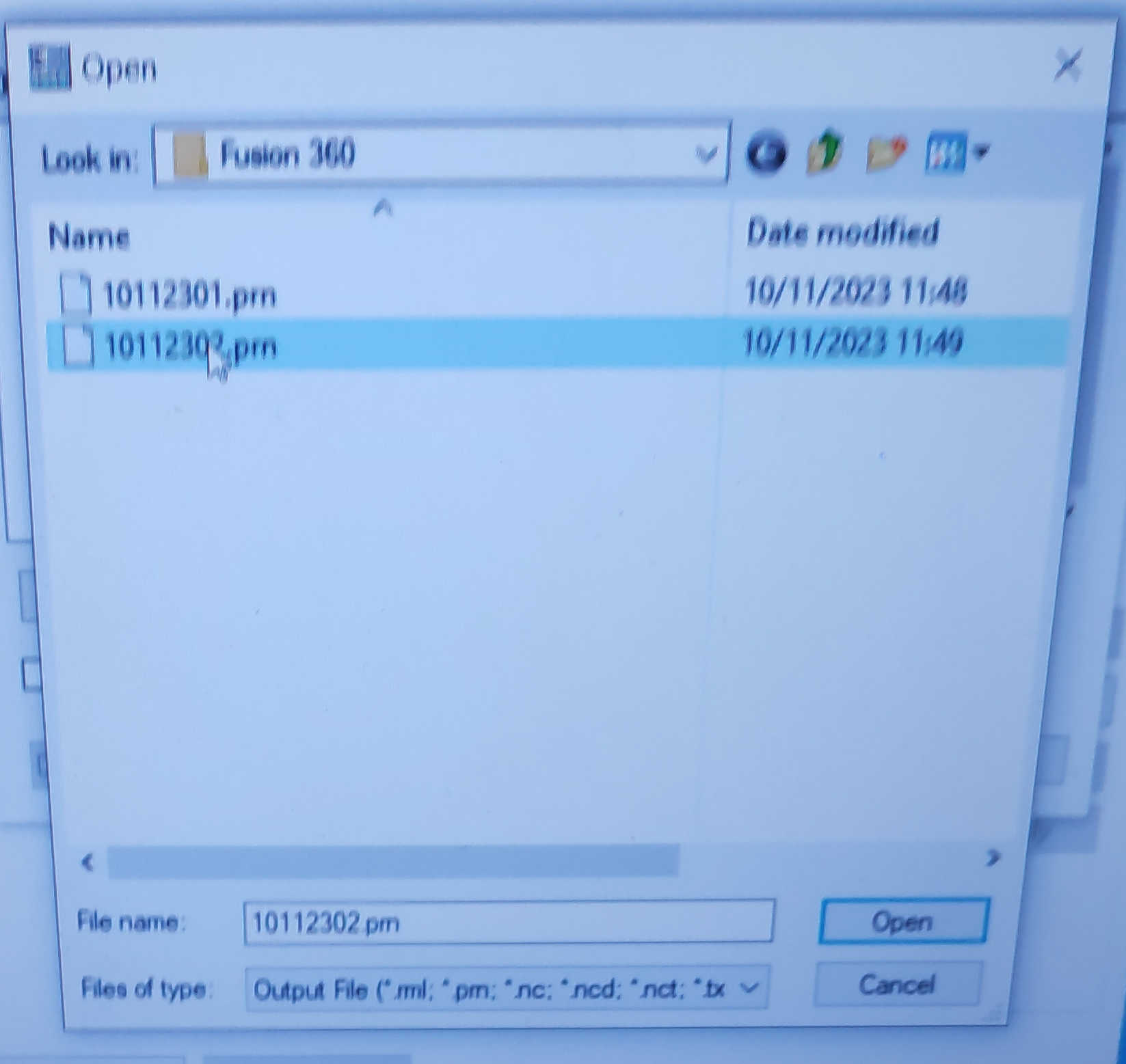
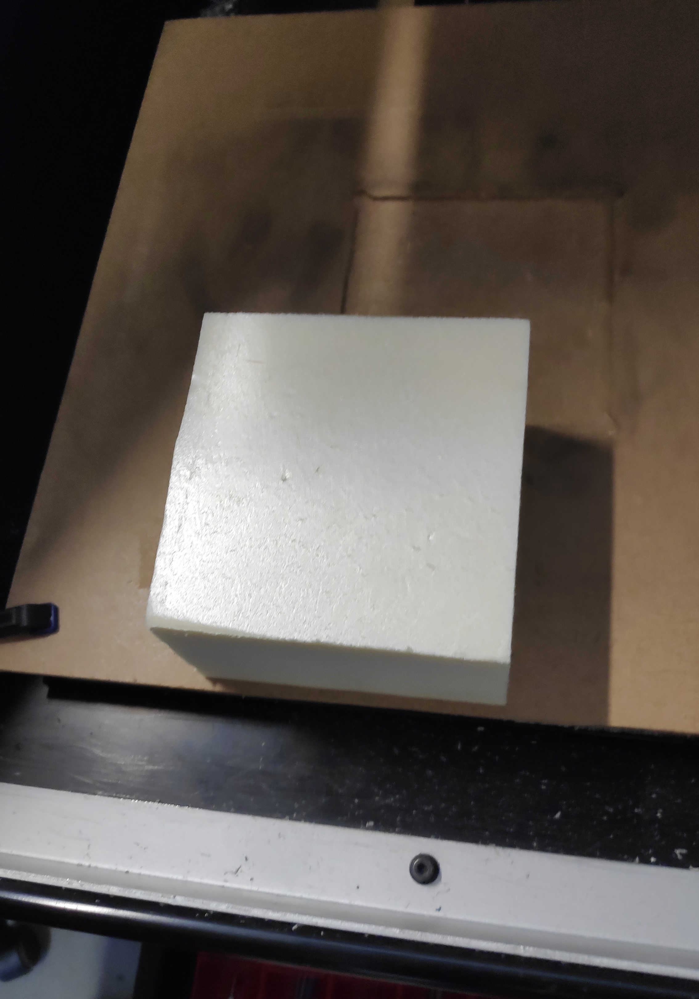
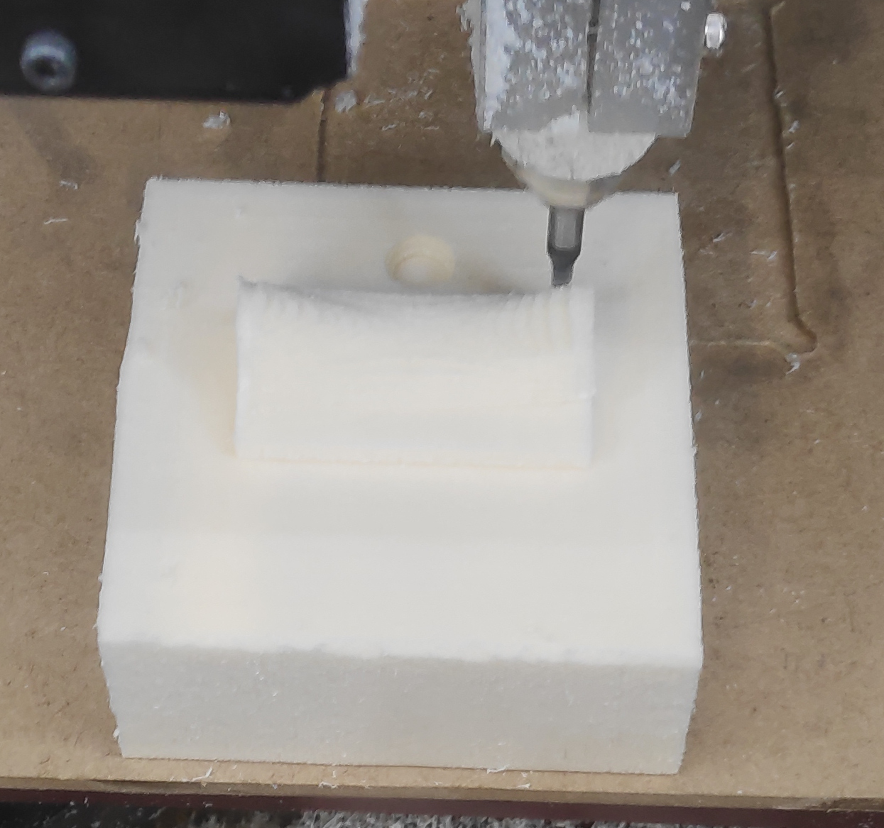
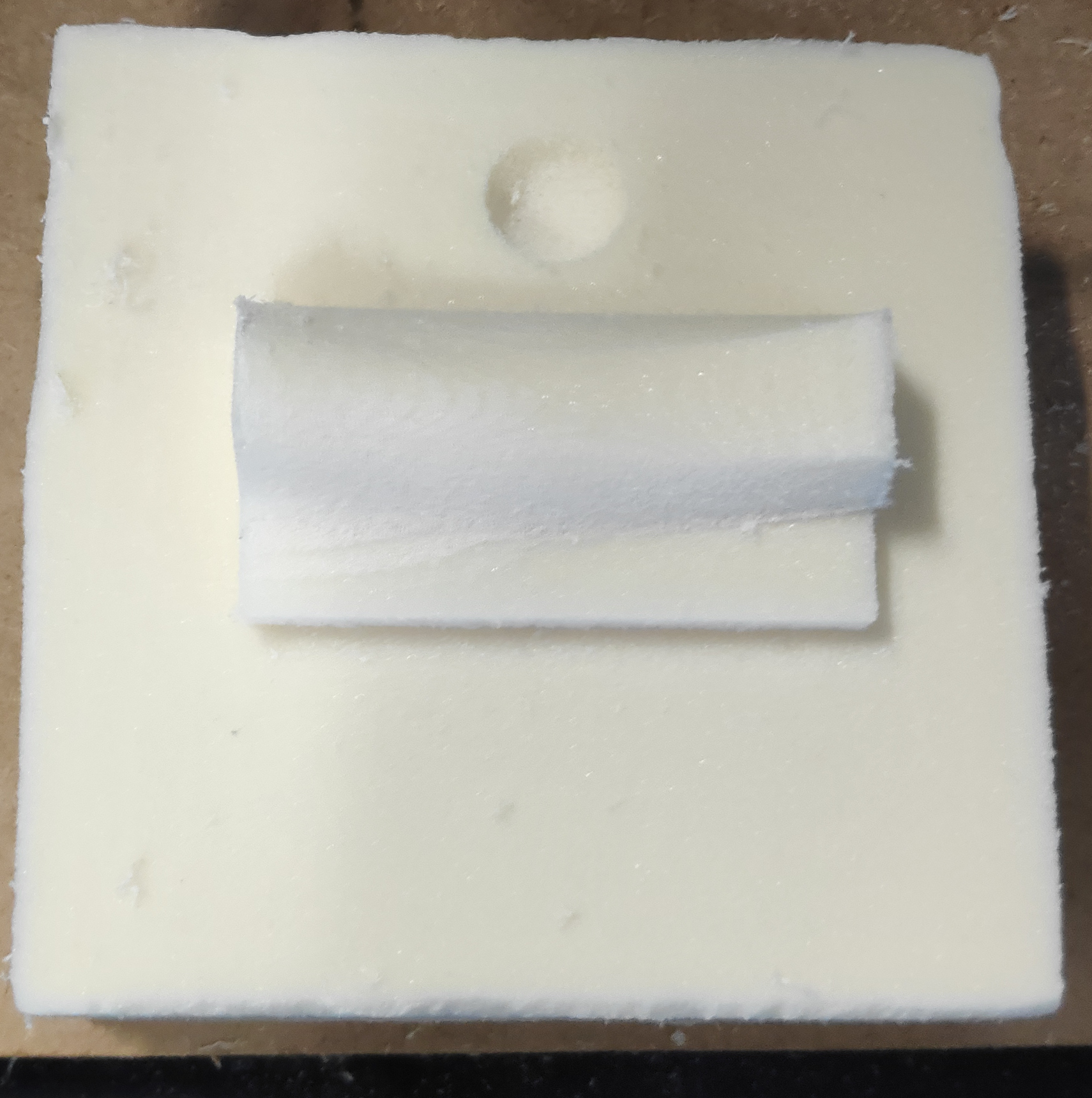
After the first job passed, I opened the CNC mill and cleaned the interior with a vacuum cleaner. I than changed the tool head to a ball head bit for the next job. Next I calibrated the CNC mill for this tool bit. Due to the positioning of the tool bit, I only had to calibrate the z height with the puck and was good to go for the second job. I did the same step to load the new job file and started the machine. The final product will look like this:
Here are the following files used: