Week 4 - Laser Cutting
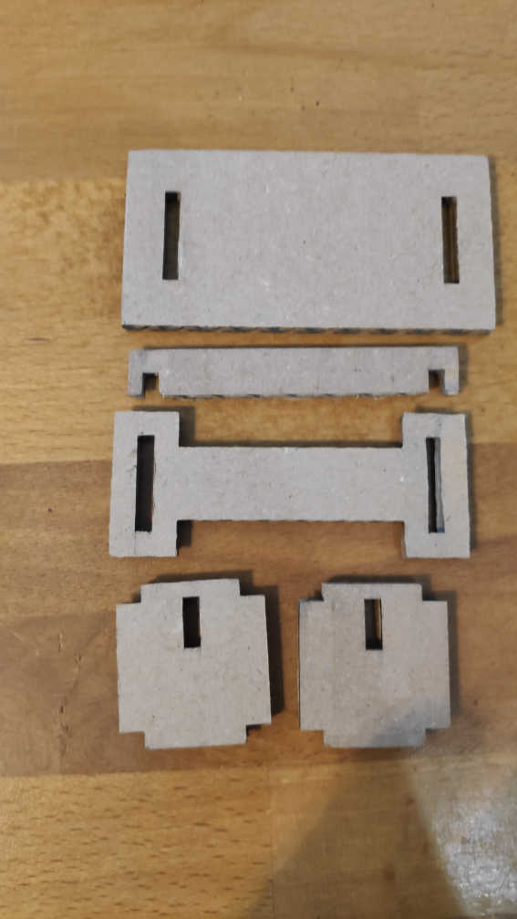
Task for this week was to create a “Press Fit kit” using cardboard. To get a cutout from the cardboard, the usage of the laser cutter was mandatory. As a simple shape I decided to build a small cardboard, which could be put together with a few parts.
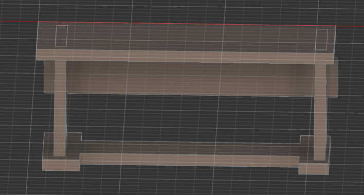
For the design of the table I first created a 3d form in ”Fusion 360” to get an idea, where to place each cardboard face for the table and where the connection between each piece should be. For this I created a the top of table, 2 legs, a support beam to hold both legs together and an additional foot, which connects both legs too.
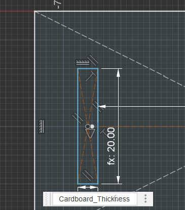
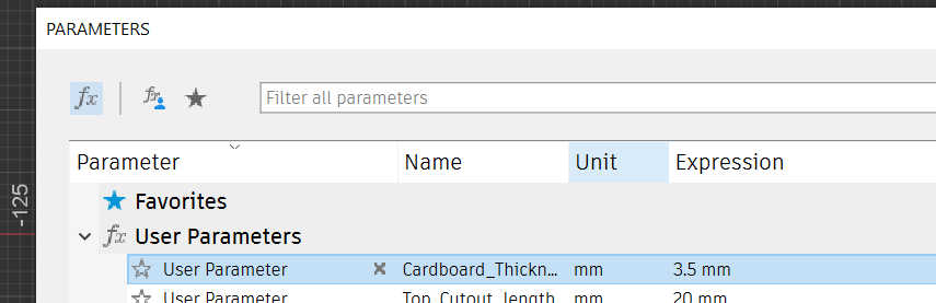
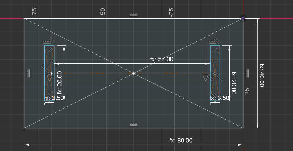
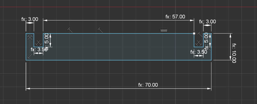
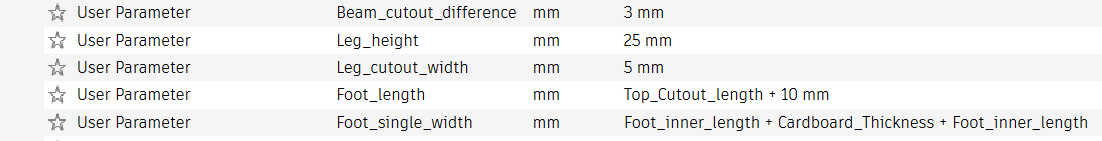
Based on the 3d Design I created for each part a sketch in the same file with the right dimension. I created a the top of the Table with to Cutout for each leg, so I could stick on it. For the sizing for the cutout, I had to make sure that the thickness of the cut-out depended on the cardboard thickness. To do this, I used the parameter tool in “Fusion 360” to create variables for each defined sizing of the object. I defined a user Variable as the cardboard thickness, which increase width of the cutout depending on the value. I used the rest of the variables to define lengths other parts of the table.
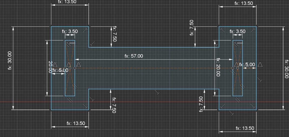
Than I created the support beam using the same method, but as a separate sketch, to make the exporting a placing later on easier. For the inner length between each foot I reused the define variable length between the cutouts from the table, to get the right aligning of both legs. And I also used the cardboard thickness variable to define the wideness of the cutout.
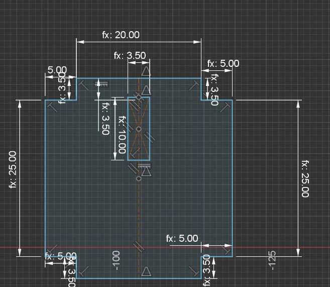
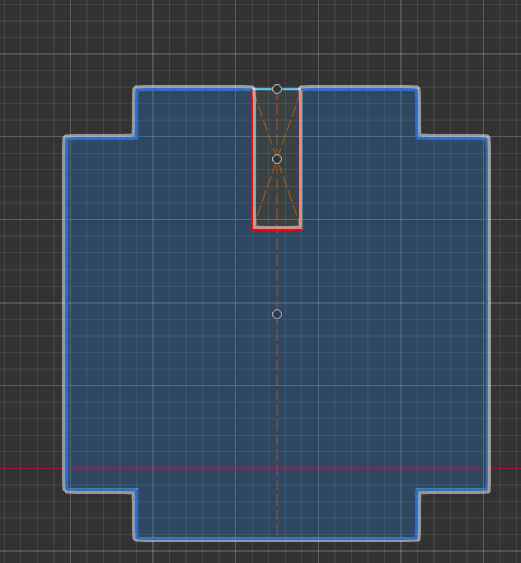
As third i designed the legs of the table by using one sketch. Because each leg worked the same independent from the side it is on, I simply had to create on sketch for both. I created a cutout with height of the beam and the width of the cardboard, so I could slide the beam from each side and snap it downwards on the legs. At the assembly of the piece, this could be optimized , by just slicing form the leg upwards down to keep the beam more locked in place.
Lastly the table needed some legs to stand on. I used the same steps as before, but in addition I used a simple expression to get the length between both leg cutouts. To define an expression I used the user parameter again, but instead inserting a number, I used an expression. For example the width of each foot is defined as: thickness of the cutout + padding left + padding right. This helps for scaling the foot width accordingly with the cutout inside it.
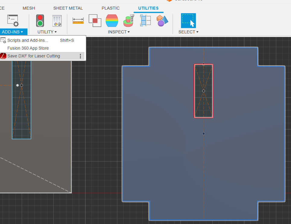
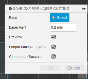
To export the model for laser cutting, each sketches needs to be extruded first. This creates an exportable face, than can be read from the “DXF for Laser cutting” add-on. Using this add-on you simply select the face you want to laser cut and select “Save as DXF for Laser cutting”. Than type in kerf, which is created by the laser and press ok. For this laser the kerf was around 0.2mm.
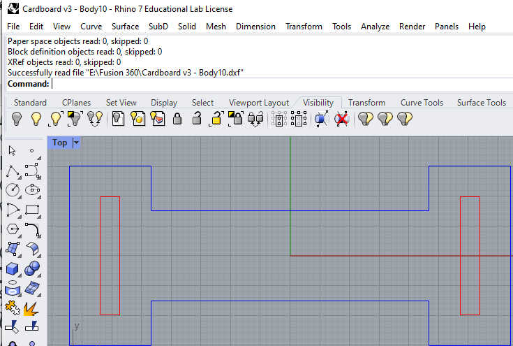
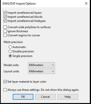
Before printing, this file format needs to be converted to be printed, because the laser cutter software cant read .dxf files. To convert it , I used “Rhino”. By double clicking the .dxf file or importing it directly, rhino will load the file. At startup the software will ask for the measurements to translate it to. I used millimeters, so I selected it as a layout and model units. Than select the window, which shows the right axis of the model and start the print. This will automatically start the laser cutter software from “Epiloge Laser” and import the file with the right conversion.
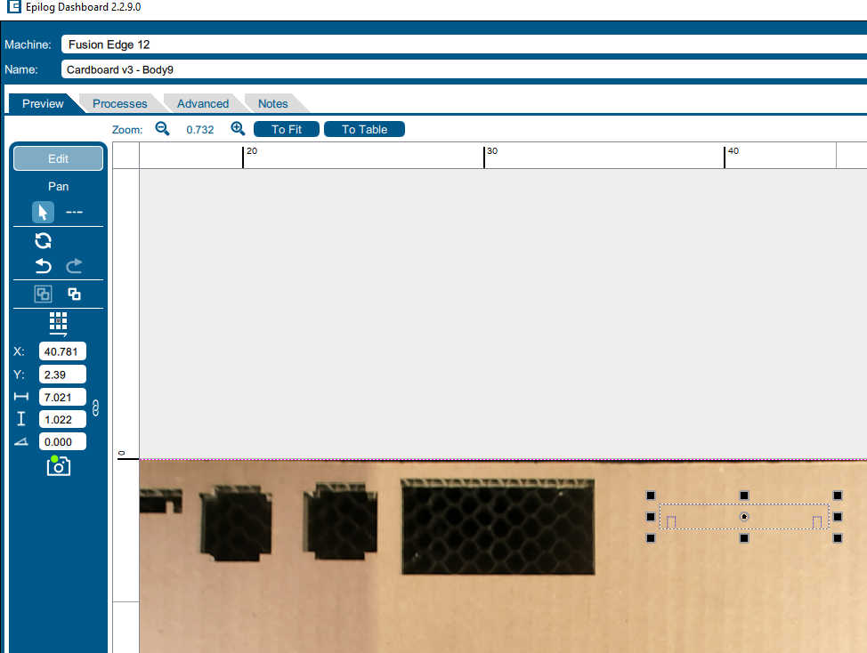
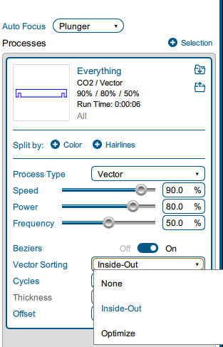
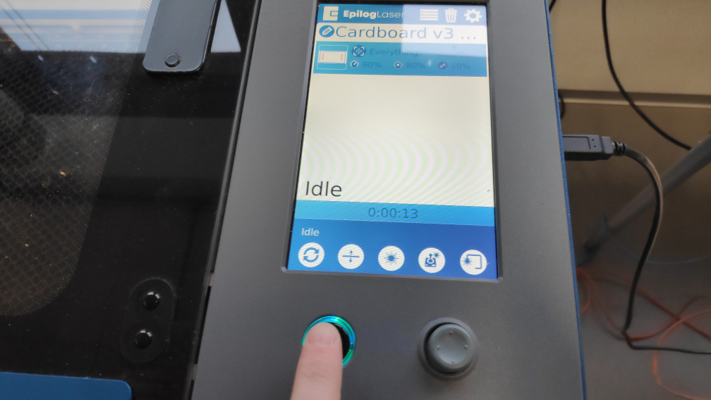
Inside the laser Cutter Software you have to first select the right laser cutter, if there mutabili cutters connected. For this task I used the “Fusion Edge 12”. Next I placed my shape on free position on the “canvas”. By using the camera of the laser cutter I could place it roughly on the actual cardboard. The general setting for this 3.5mm cardboard for cutting were a Speed about 90% and Power of 80 % cutting at a frequency of 50%. All my models didn't need laser engraving, thus I didn’t need to split my jobs. I used some cutouts inside my faces, so I needed Vector sorting from inside out. To auto-foucus the laser, I used the build-in Plunger to calibrate it. Lastly I selected print, which sends the job to the cutter.
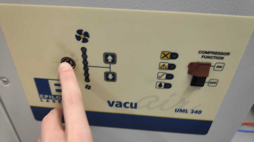
I select the file on the laser cutter over the display. Before the starting to cutting with the laser, check and activate the ventilation, so the lens wont get dusted. Than I pressed the start button to start the cut. Because cardboard is a flammable material I stayed near the laser cutter until it was finished cutting.
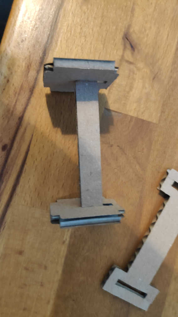
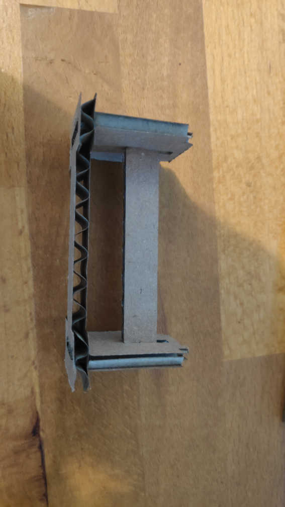
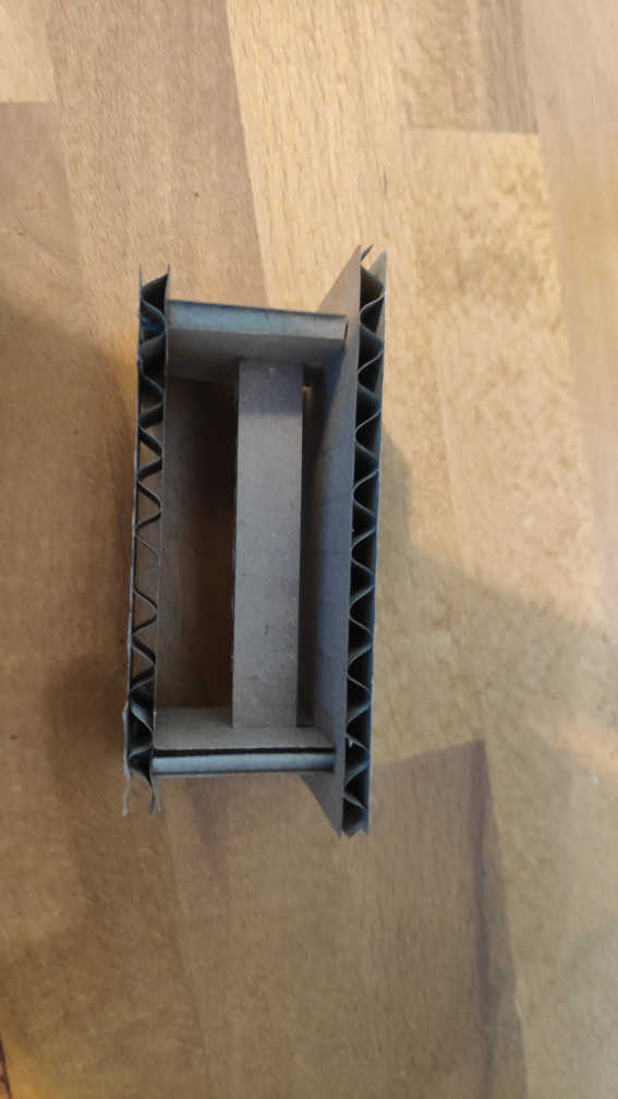
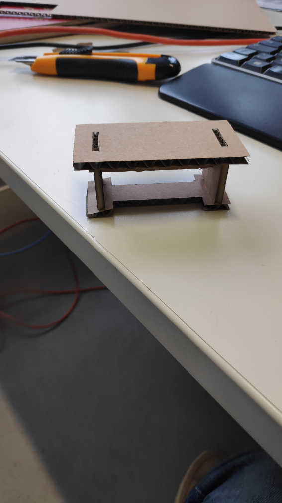
The final Assembly step by step looks like this. First connect both legs with the beam. Than put both legs on the feet cutout. Lastly place the top of the table on top. If the cardboard has the right thickness it will slide together easy and will stick together without any additions.
Here are the following files used: