Week 2
For this week I created a rough preview of the clock with a 3d model in “Fusion 360”. This model can than be used to plan for needed electronic components and gives a rough idea what actual size it would have.
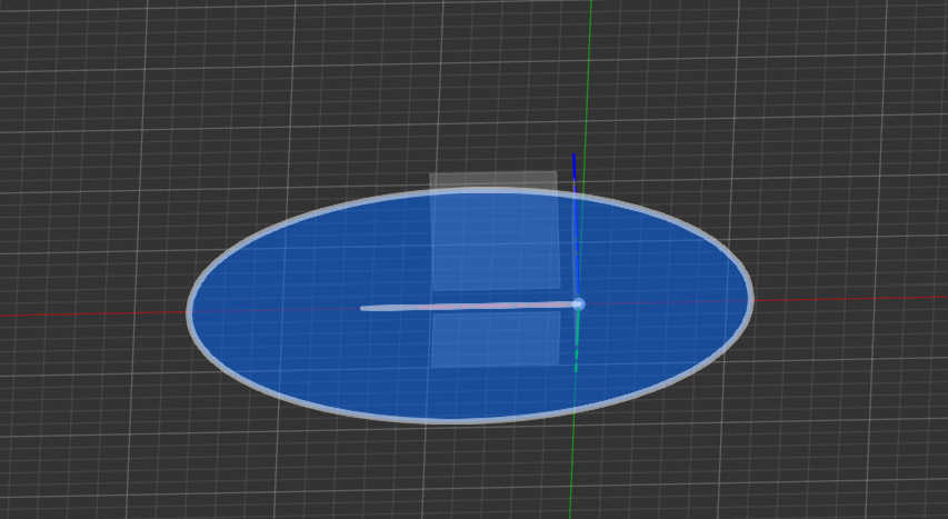
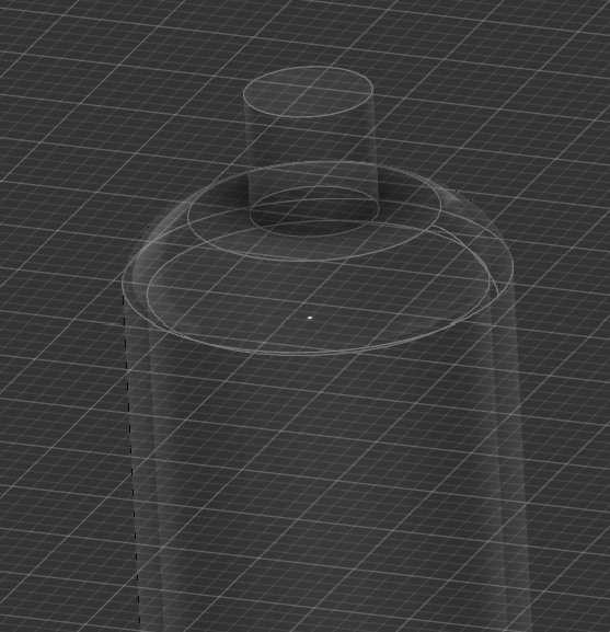
Firstly I create the nix Tube which represents the display of the clock. For this I needed a glass Body, which contains the display and the actual display inside the tube to show the time. The Glass body needed to fit the display, which is roughly represented in the model. For this I used a sketch to create a circle and extrude it. The extrusion is than set to “New Body” to create the first Geometry.
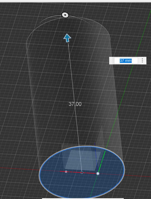
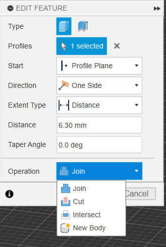
To create the leftover from the glass forming process, I used the same step as above to extrude a second cylinder. The extrusion is set to “join” to add to the glass body. For hollowing the cylinder I used the same step with a smaller circle inside the existing circle and extrude it inside the cylinder, creating a cutout. For this to work set the cylinder to “Cut”, which only cuts the existing Geometry.
After this I bevels the glass multiple times to create the round shape. I first beveled the lower cylinder top by selecting the outer edge and use the Fillet-Tool. Based on what edges is rounded, fillet will be concave or convex.
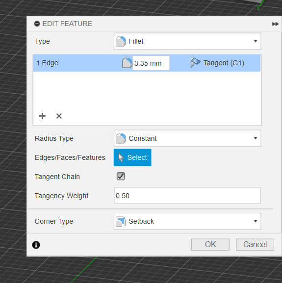
For beveling every Edge on the top it should ended up looking like this.

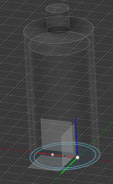
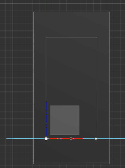
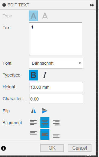
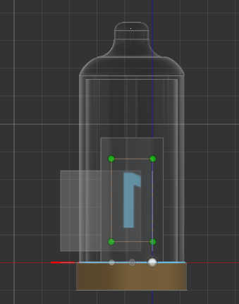
Secondly I created the Display, which also firstly stared with a sketch consisting of 2 Rectangles. The inner rectangle represent the screen and outer rectangle as the screen edge. Both rectangles are than extruded with the length. With the sketch tool I added a placeholder number to the display, to show its function. For this I created a number on the surface of the screen and used the “text”-Tool.
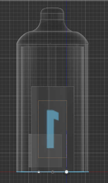
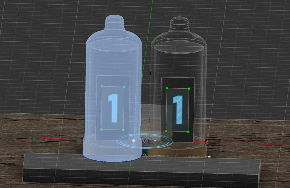
I than added a cylinder as a base and finished the “Nixie Tube”. I also used the “Move-Tool” to center display inside the cylinder and to move it upwards.
The base of the clock is just one big Rectangle, which has the buttons and display mounted onto. For
this I used the same step as the display to create it. I consist of a rectangle sketch, which than is
extruded.
The look of the box will only be changed at the end of all steps, to make the placement of all
objects on
the box easier.
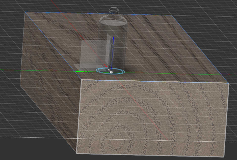
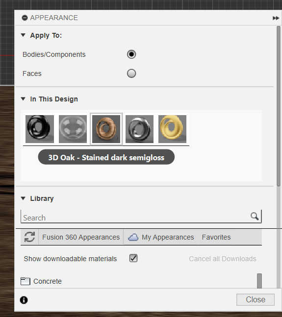
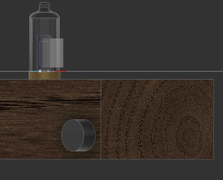
To let the box look like wood I applied a material to the box by right-clicking it and selecting “Appearance”. I than dragged and dropped the wood material on the object which creates this look.

I than aligned the “Nixie Tube” with the Box top-center using the move-tool with the “point to point” Setting. By selecting the center of the Box as the target and the “nixi-Tube”-Socket midpoint as the origin, the “Tube” snapped to the center.

For this step I added some construction lines to help with the placement of the buttons. To archive this I created a sketch on the box side, which consist of lines. Because this are only for placement I converter them into construction lines with the shortcut (X).
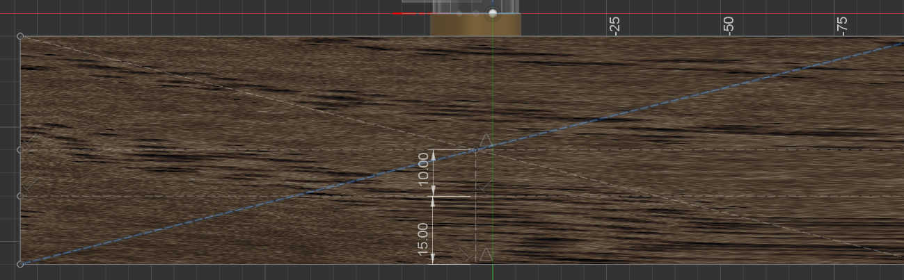
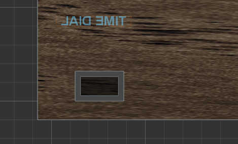
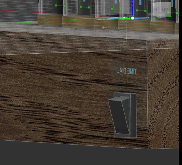
Next step I created a dial, which can be used for changing the time. I just created a Cylinder and placed it on the box using the existing construction lines. Its important to move it with point to point to the box, for it to change its height-position according to construction lines,if there getting modified. Afterwards Translation can be used to move it closer to the center or away.
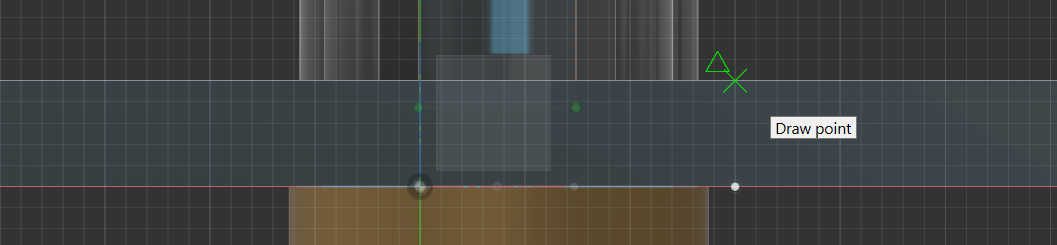
To stop/snozze the alarm I need a button to press it, so I created a this button by just simply creating a rectangle. I than placed it centered on the box using the construction lines created 2 steps before and a newly created point on the button itself to snap it to “point to point”. To create this point, I created a sketch on the surface of the button facing the same as the box outer side and used add Point. By dragging the mouse courser along the bottom line of the surface, the point automatically snaps to the middle of the linen.

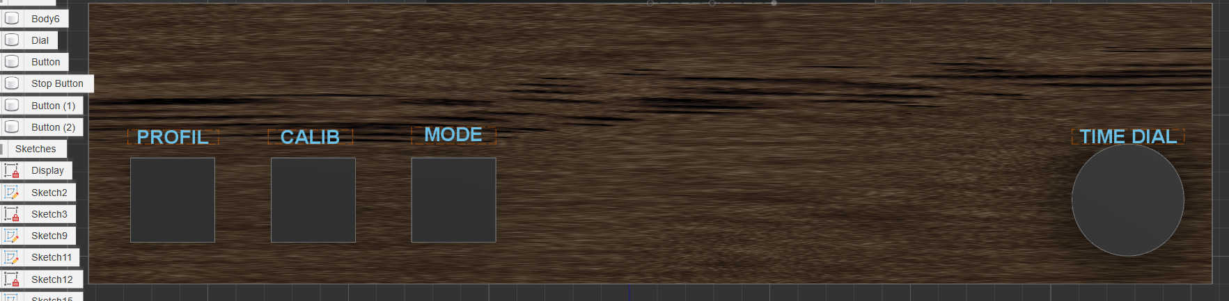
For the last Buttons I created a stand in button, from which I can created an array of buttons, with each having the same spacing. To do it create a rectangle an extend it creating a button shape. This button than need to be copied, so I used the “Rectangle Pattern” extender, which extended a selection of objects by copies them in 2 axes. Firstly an axis needs to be select, on which it should be expanded upon. After this the amount and the direction needs to be selected for each axis. I only needed one axis, so only changed the first axis (x) amount to 3 (including the object itself) and set the direction to one direction. Furthermore I edited the offset settings, to get an equal spacing.

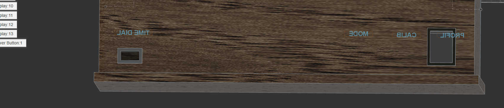
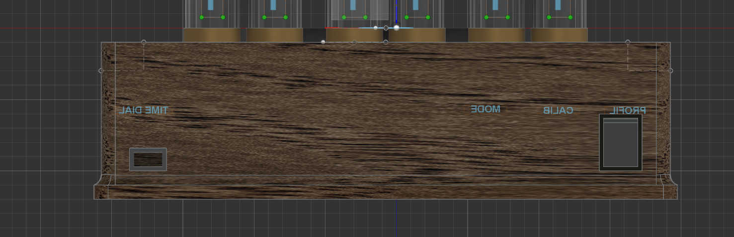
I than added some descriptive text for each button with a sketch to the surface of the box.
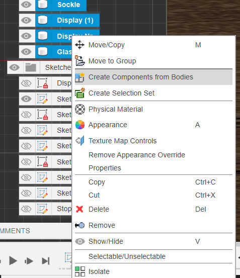
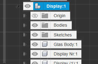
Because I than new where the placement of each object where, I changed the positioning of the “Nixi-Tube” and duplicated it to create fully display for the time. I firstly converted each body part of the “nixi tube” into a component, so I could use it more easier. For this I selected all body parts and right-clicked to convert it to a component. Than I parent the components to the socket.
I copied the component once with just using the shorcuts str-c and str-v. I than created a sketch with construction lines and a point to get an equal distance from both “Tubes” to the middle of the box. With the move tool I snapped both “Tubes” to each end of the linen.
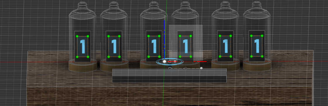
I than used the “Rectangle Pattern” extender again to create 2 more Duplicate with a different spacing. I set the direction to symmetric to get tubes on both sides of the extension.
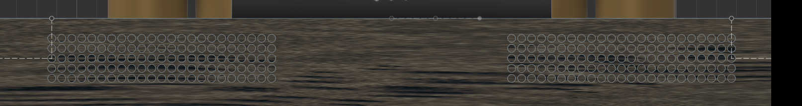
To listen to the alarm the box needs some speaker holes. For this I created a circular sketch on the front Face of the box and extruded the hole inside the box. To place the circle I used some construction line and snapped the circle point to point onto it. To create many holes a for an array of cutouts I used “Rectangle Pattern” again. I used the 2 Axes with a one direction in the x axis and a symmetric direction for the z Axes. This creates a Rectangle form filed with circle cutouts. I copied this step also cut on the left side of the box.
To power the clock I need a port to connect a cable. I guessed that it would be probably a micro USB or USB-C cable, so I made a rectangular cutout on the backside of the box, with a rectangle Sketch and extruded it. I added a border around it indicate that it port.
The last button I added was a power switch to deactivate the clock when needed. For this I used a rectangular casing and added a cuboid inside it. I Rotated the cuboid, so its looking like a switch, which is activate in one direction.
Lastly I decorated the box to make it more interesting. I added a base, which I created from a rectangular sketch and extrude it. I than rounded each corner on the side with the fillet-Tool. Than I rounded the base top with a concave from by selecting the inner edge between the box and the base and beveled it.
The Base Component to create it would take:
-
1x Switch
-
3x Small Button
-
1x bigger Button
-
1x Potentiometer
-
1 or 2 x loudspeaker
-
6x LED Display
either pure Numbers or fully LED
-
1x Power Cable port
-
1xCrystal oscillator
The "Fusion 360" file can be get here: Final Project Sketch.f3d